


13
2. Functions
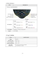
2-1 Function Descriptions
FUNCTION
SPECIFICATION
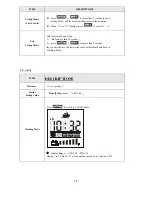
1
Temperature
“
C” / “
F” modes
2
Clock
Hour / Minute display and setting
3
Odometer
Trip Meter
ODO
(99999 max),
TRIP
(999.9 max)
Sum of distance and time
4
Speedometer
7 Segment display (2 1/2 1 decimal)
“
km/h
” and “
mph
” symbol
5
High /Low Speed
& Turn Status
Indicated as icon
and
6
Power Indicator
Battery remaining capacity and charging indicator
(6 s Battery icon)
7
Headlight
Blue LED
Including “Power-Saving” mode
8
Position Light
Orange LED
Placed inside headlight, used while rainy or gloomy weather
9
Brake Light
Including “Brake-Mode” and “Parking Mode”
10
Left-Right
Direction
Indicators
Green LED
Flash mode
Auto switch-off after 30 seconds
11
Parking Light
Red LED
Including “Parking Mode”
Right/Left indicators flash simultaneously
12
Malfunction Messages
Red LED
Malfunction code:
7 Segment display (1digit) + warning symbol
13
Power-On-Self-Test
All LED illuminated