Blue Sky International MK II Скачать руководство пользователя страница 12

Page 12

The  following  sysetm  calibration  instructions  are  for  a  bass-managed 
speaker  system,  such  as  Blue  Sky’s  ProDesk,  Sky  System  One,  or  Big 
Blue system.


There are three steps to the calibration procedure:


1 - Setting the electrical / digital signal level


2 - Setting the reference level (REF)


3 - System Acoustic Level Setting

The instructions included with in this manual detail two sperate ways to 
do step 3.  One method uses bandwidth limited test files and requires 
only a SPL meter.  The other method uses full-bandwidth pink noise and 
requires the use of a 1/3 octave real time analyzer (RTA), along with a 
SPL meter.  

Before  starting  the  calibration  procedure  you  will  need  to  download 
BlueSkyTestFiles.zip (18MB file) by going to www.abluesky.com/calibration. To 
download the test file, “Right Click” the file, select “Save Target As” and the file 
will begin downloading.  Once downloaded, un-zip the test files and either 
burn the test files to a CD or import them into your DAW. 

BlueSkyTestFiles.Zip Includes 4 files:

• 

1000Hz SINEWAVE -20dBFS.wav – a 1kHz file recorded at -
20dBFS for electrical calibration

• 

40-80Hz PINK NOISE -20dBFS.wav – a 40Hz to 80Hz bandwidth 
limited pink-noise file recorded at -20dBFS

• 

500-2.5kHz PINK NOISE -20dBFS.wav – a 500Hz to 2.5Hz 
bandwidth limited pink-noise file recorded at 20dBFS

• 

Pink Noise full bw -20dBFS.wav – a full-bandwidth pink-noise file 
recorded at - 20dBFS

These  test  files  are  all  mono  files.    Please  make  sure  you  hard  assign 
them to the left and then the right (etc.), not both channels at the same 
time. If you are using a CD player as your source, use only one channel 
of the CD player.  All test signals are recorded at –20dBFS including the 
1 kHz sine wave tone. The sine wave tone is used to set the electrical 
output level throughout the signal path, right up to the point you get to 
the speakers, while the various pink noise signals are used for acoustic 
measurements and calibration.


THEORY

The purpose of calibration is to adjust the overall electroacoustic system gain 
so that 0dBVU of electrical signal level equals a certain acoustic level at the 
listening position. Since most recording media is now digital, the reference 
electrical signal level is usually –20dBFS with 20dB of headroom. The reference 
SPL level however can vary based on the delivery media and speaker type.   

Please note that the bandwidth limited signals that have been provided, limit 
many of the room interaction affects often associated with measuring SPL using 
broadband pink noise.

*Also, please note that the LFE channel gain in a 5.1 system varies from 
0dB to +10dB, depending on the encoding format that is being used.  
Since the LFE channel is not calibrated as a separate entity, the LFE gain 
will  not  affect  system  calibration. 

  For  more  information  about  the  LFE 

channel refer to page 15  [Additional Surround and Setup Information].

T�e common ca�ibration �eve�s

IMPORTANT  NOTE:  The  individual  channel  level  trims  (+/-  6dB)  in  the  BMC 
MK  II,  are  “OUTPUT”  channel  level  trims,  and  are  used  to  adjust  the  relative 
level between the SUB and SAT in .5 dB increments.  The reason this fact is 
important, is because in certain applications, such as in a film setup where the 
surrounds may need to be at a lower level as compared to the front speakers, 
the level adjustments for the surrounds must be done before the signal hits the 
BMC MK II.  This is because if you adjust the surround level only with the BMC 
main channel output level trims (main channels = L, C, R, LS & RS), the SUB and 
SURROUND level may not match.

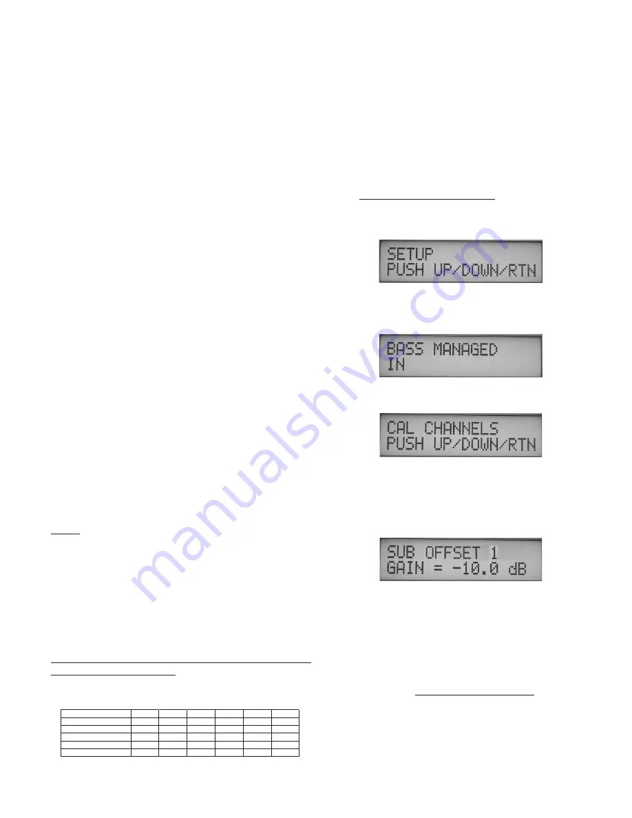
SETTING THE ELECTRICAL / DIGITAL SIGNAL LEVEL
Step 1


TURN OFF THE MONITORING SYSTEM

Step 2 

“Bass Managed IN” - 

Hold down the SELECT button for 5 seconds 

to  enter  SETUP  MODE.    Then  press  select  3  times,  or  until  the 
display reads “SETUP” (shown below).


Press the UP or DOWN ARROW keys until the display reads “BASS 
MANAGED IN”. If the display reads “BASS MANAGED OUT” then 
press the YES button to turn it on.

Step 3


Now press the SELECT button 3 times, or until the display reads 
“CAL CHANNELS”. 


Press  the  DOWN  arrow  button  once,  or  until  the  display  reads 
“SUB  OFFSET  1”  and  then  use  the  “-”  button  to  set  the  offset  to 
-10dB.  This setting will give the subwoofer / LFE summation buss 
the greatest amount of electrical headroom.  If it turns out that your 
subwoofer doesn’t have enough electrical gain to get the desired 
output, then you may need to set this back to 0dB of offset.

Step 4 

  Remove  all  eq  and  dynamics  from  the  signal  path  and  set  all 

controls to zero / unity gain.  Play the 1kHz Sine Wave, hard assign 
it to the LEFT channel only, and adjust the output fader so that the 
output meter reads -20dBFS. If you are using an analog console, set 
the output level to 0dB VU.  Then hard pan the signal to the center 
channel output and repeat for the center channel (then repeat for 
the  each  of  the  remaining  channels).   

Once  calibrated  do  not 

move the output faders.


Step 5 

Mute everything and make sure the 1kHz tone is OFF .

11.  5.1 System Ca�ibration

L

C

R

LS

RS

SUB*

Movie Theatrical release

85dB

85dB

85dB

82dB

82dB

85dB

Movie DVD release

85dB

85dB

85dB

85dB

85dB

85dB

Broadcast / 85dBc or

78dB

78dB

78dB

78dB

78dB

78dB

Music (Stereo)

85dB

85dB

85dB

Music ( 5.1)

85dB

85dB

85dB

85dB

85dB

85dB

Содержание MK II

Страница 1: ...B ue Sky Internationa 70 Sea Lane Farmingdale NY 11735 www abluesky com Owner s Manua Version 1b August 5 2005 Bass Management Controller MK II ...

Страница 2: ..._ _ _ _ _ _ _ _ _ _ _ _ _ Page 7 8 Software Features_ _ _ _ _ _ _ _ _ _ _ _ _ _ _ _ _ _ _ _ _ Page 8 9 5 1 Speaker Placement _ _ _ _ _ _ _ _ _ _ _ _ _ _ _ _ _Page 10 10 5 1 System Wiring Information Diagram_ _ _ _ _Page 11 11 5 1 System Calibration _ __ __ __ __ __ __ __ __ Page 12 12 Additional Surround Setup Information_ _ _ _ _Page 15 13 Dual BMC MK II I O Unit Setup_ _ _ _ _ _ _ _ _ _ _ _ _Pag...

Страница 3: ... of any kind on the product 11 SERVICING Do not attempt to service this product yourself Opening or removing covers including any over bottom or side speaker drivers may expose you to dangerous voltage or other hazards Refer all service to qualified service personnel 12 DAMAGE REQUIRING SERVICE Unplug this product from the wall outlet and refer servicing to qualified personnel under the following ...

Страница 4: ...ner s Manual This manual addresses setup and operation of the Blue Sky BMC MK II This product includes several performance and operational changes when compared to the original Blue Sky BMC We ask that you read this owner s manual carefully heed all warnings and contact Blue Sky International if you have any comments or questions Contact information can be found on page 19 or you can visit www abl...

Страница 5: ... 9 10 11 12 13 The Blue Sky BMC MK II has two operating modes These two modes are referred to as USER and SETUP Some of the buttons on the remote have two distinct functions depending on what mode the BMC MK II is operating in The Software Features on page 8 and 9 explains these functions in greater detail 1 RJ 11 Main BMC Control Output Connect this plug to the Main BMC I O unit with the supplied...

Страница 6: ...ntrol Knob will bring the system out of the reference setting SETUP MODE In the PRESET MENU this key is used to change the letters in the CHANGE NAME preset sub menu See the Software Features section on page 8 and the 5 1 System Calibration Section on page 12 for more information 11 LS left surround SELECT Button USER MODE The LS button activates the solo function for the left surround output When...

Страница 7: ...just the relative level between the SUB and SAT in 5 dB increments The reason this fact is important is because in certain applications such as in a film setup where the surrounds may need to be at a lower level as compared to the front speakers the level adjustments for the surrounds must be done before the signal hits the BMC MK II This is because if you adjust the surround level only with the B...

Страница 8: ...MENU Moving the master gain control knob pressing mute or pressing the REF button again will bring the system out of the reference setting When the REF function has been activated the REF LED will be ON and the display will show REF GAIN and then state what that GAIN possition is 10dB in the example below For more information about how to detirmine the optimum reference level setting please follow...

Страница 9: ...ARROW PRESET MENU The BMC MK II has a total of 4 presets available The presets store all level and calibration settings for the BMC along with preset name SUB level offset bass management IN OUT and LFE GAIN The main display will always display what PRESET is in current menu when in USER MODE and when not in MUTE REF or SOLO mode as shown below in this case PRESET 1 Whenever you are in the SETUP M...

Страница 10: ...osition and slightly behind the mix position For larger rooms it may also be desirable to use multiple surround speakers as an array Satellite Speaker Monitoring Height Recommendations It is recommended that all of the satellite speakers be placed at or about seated ear height as shown in Figure 2 If it is not possible to place the speakers at or about seated ear height please aim the speakers at ...

Страница 11: ...nnect your console workstation or other sources to your Blue Sky BMC MK II Foil shielded cables such as Belden 8451 8761 or 9501 should do quite well Other high quality cables are available and those that incorporate better shielding will yield an overall higher noise rejection lowering your systems susceptibility to external interference Another important tip to keep in mind when wiring your syst...

Страница 12: ...ink noise Also please note that the LFE channel gain in a 5 1 system varies from 0dB to 10dB depending on the encoding format that is being used Since the LFE channel is not calibrated as a separate entity the LFE gain will not affect system calibration For more information about the LFE channel refer to page 15 Additional Surround and Setup Information The common calibration levels IMPORTANT NOTE...

Страница 13: ... knob until the SYSTEM GAIN equals the gain noted in step 4 Release the knob being careful to not nudge it and then press YES when the menu reapears You have now successfully stored the preset REF level Press CANCEL to exit setup and then press the REF button to confirm the setting is correct The display will read REF GAIN with the gain setting below shown below The REF LED will also be ON SYSTEM ...

Страница 14: ...the display reads MUTE CHANNELS as shown in step 1 Press the down arrow button one time or until the display reads MUTE SUB 1 Press the NO button on the remote The display will read MUTE SUB 1 NO as shown below Now MUTE the other 5 channels Left Center Right LS RS Step 6 Confirm that the gain knob on the remote is set to the REF setting as determined in the section titled SETTING REFERENCE GAIN on...

Страница 15: ...lthough there may be some creative reasons to use the LFE from time to time It is important to note that no significant audio should be sent exclusively to the LFE channel The reason for this is that if a Dolby Digital audio track is folded down to 2 channels which can happen if a consumer doesn t have a surround system the LFE channel will not be added to the fold down mix all other channels will...

Страница 16: ...where the bass is being routed from the MASTER I O Unit 1 to the AUX I O Unit 2 This can be any system beyond 5 1 and all the way up to 10 1 The general overview with regard to connections and setup is shown on page 17 Important notes for this type of setup 1 SUBWOOFER GAIN 1 should be set to 0dB in the CAL CHANNELS menu 2 Overall system subwoofer level should be set on the BMC I O unit connected ...

Страница 17: ... ELECTRIQUE NE PAS OUVIR pm3 L U C A S F I L M R PUSH PUSH PUSH MAIN AUX LFE Input 10dB or 0dB Bass Managed LFE summed input from main BMC unit LFE should be set to 0dB of gain to sub to LFE IN MAIN BMC Unit 1 Wire the main channels to this BMC Subwoofer level trim should be set to 0dB Overall system subwoofer level should be adjusted on the AUX BMC via remote LFE gain can be set to either 10dB or...

Страница 18: ...ype 2nd order Linkwitz Riley High Pass Filter Cutoff 80Hz Low Pass Filter Type 4th order Linkwitz Riley Low Pass Cutoff 80Hz LFE Input Gain 0dB 10dB Selectable Low Pass Filter 4th order 120Hz Input power 120 VAC 60HZ 240 VAC 50 60HZ 15 Watts Voltage set at the factory 14 Technical Information 1 10X GAIN 24 dB OCT 120 HZ LOWPASS DIGITALLY CONTROL ANALOG POT INPUT SELECT INPUT OUTPUT 24 dB OCT 80 HZ...

Страница 19: ...due to non factory packaging 4 Include a legible note stating your name shipping address no P O boxes daytime phone number RA number and a detailed description of the problem including how it can be duplicated 5 Write the RA number on the top of the carton 6 Ship the product to the address below We recommend United Parcel Service UPS Please insure the product regardless of shipping method Blue Sky...

Страница 20: ...Blue Sky International 70 Sea Lane Farmingdale NY 11735 www abluesky com ...

Отзывы: