


Outdoor Patio Heater Model No. GWU9300H
Contact 1.800.762.1142 for assistance. Do not return to place of purchase.
Note:
the burner may be noisy when initially turned on. To eliminate excessive noise from
the burner, turn the control knob to the pilot position. Then, turn the knob to the level of heat
desired.
When heater is ON:
Emitter screen will become bright red due to intense
heat. The color is more visible at night.
Burner will display tongues of blue and yellow flame.
These flames should not be yellow or produce thick
black smoke, indicating an obstruction of airflow
through the burners. The flame should be blue with
straight yellow tops.
If excessive yellow flame is detected, turn off heater
and visit www.bluerhino.com or call 1.800.762.1142.
Re-lighting
Note:
For your safety, control knob cannot be turned “OFF” without first depressing control
knob in PILOT position and then rotating it to “OFF”.
1. Turn control knob to “OFF”.
2. Wait at least 5 minutes, to let gas dissipate, before attempting to relight pilot.
3. Repeat the “Lighting” steps.
Shut Down
1. Turn control knob clockwise to pilot. (Normally, burner will make a slight popping sound when
extinguished.) Burner will extinguish but pilot will remain “ON”.
2. To extinguish pilot, depress control knob and continue to turn it clockwise to “OFF”.
3. Turn tank valve clockwise to “OFF” and disconnect regulator when heater is not in use.
Note: After use, some discoloration of the emitter screen is normal.
Cleaning and Care
CAUTION: All cleaning and maintenance should be done when patio
heater is cool and with the fuel supply disconnected.
CAUTION: DO NOT clean any patio heater part in a self cleaning oven.
The extreme heat will damage the finish.
Notices
1. Abrasive cleaners will damage this product.
2. Never use oven cleaner to clean any part of heater.
3. Do not clean any heater part in a self cleaning oven. The extreme heat will damage the
finish.
4. More frequent cleaning may be required as necessary. It is imperative that control
compartment, burners and circulating air passageways of the heater be kept clean.
5. Spiders and insects can create a dangerous condition that may damage heater or
make it unsafe. Keep burner area clean of all spiders, webs, or insects. Clean burner
holes by using a heavy-duty pipe cleaner. Compressed air may help clear away smaller
particles.
6. Inspect heater before each use.
7. Have heater inspected annually and repairs should be made by a qualified service
person.
8. Check heater immediately if any of the following conditions exist:
a. The smell of gas in conjunction with extreme yellow tipping of burner flames.
b. Heater does not reach proper temperature.
Note: At temperatures less than 40ºF, heat output will be reduced.
c. Heater’s glow is excessively uneven
d. Burner makes popping noises during use.
Note: A slight pop is normal when burner is extinguished.
9. Carbon deposits may create a fire hazard. Keep dome and emitter clean at all times.
10. Do not clean heater with combustible or corrosive cleaners. Use warm, soapy water.
11. Do not paint engine, engine access panel or dome.
12. This heater should be thoroughly cleaned on a regular basis.
13. After a period of storage and/or nonuse, check for leaks, burner obstructions and
inspect for any abrasion, wear, cuts to the hose.
Cleaning Surfaces
1. Wipe surfaces clean with mild dishwashing detergent or baking soda.
2. For stubborn surfaces use a citrus based degreaser and a nylon scrubbing brush.
3. Rinse clean with water.
Note:
While cleaning your unit, be sure to keep the area around the burner and pilot assembly
dry at all times. Do not submerge the control valve assembly. If the gas control is submerged in
water, do NOT use it. It must be replaced.
Operating Instructions
Checking for Leaks
Burner Connections
Make sure the regulator valve and hose connections are securely fastened to the burner and
the tank.
If your unit was assembled for you, visually check the connection between the burner pipe and
orifice. Make sure the burner pipe fits over the orifice.
WARNING: Failure to inspect this connection or follow these
instructions could cause a fire or an explosion which can cause death,
serious bodily injury, or damage to property.
If the burner pipe does not rest flush to the orifice, please contact 1.800.762.1142 for
assistance.
Tank/Gas Line Connection
Make 2-3 oz. of leak solution by mixing one part liquid
dishwashing soap with three parts water.
Make sure control knobs are “OFF”.
Turn LP gas tank “ON” at valve.
Spoon leak check solution at all “X” locations
If any bubbles appear turn LP gas tank “OFF”, reconnect
and re-test. If you continue to see bubbles after several
attempts, disconnect LP gas source and contact
1.800.762.1142 for assistance.
If no bubbles appear after one minute turn tank “OFF”,
wipe away solution and proceed.
Before Lighting
Heater should be thoroughly inspected before each use,
and by a qualified service person at least annually.
If relighting a hot heater, always wait at least 5 minutes.
Inspect the hose assembly for evidence of excessive
abrasion, cuts, or wear. Suspected areas should be
leak tested. If the hose leaks, it must be replaced prior
to operation. Only use the replacement hose assembly
specified by manufacturer.
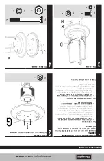
Lighting
Note:
this heater is equipped with a pilot light that allows for safer startups and shutdowns.
Pilot must be lit before main burner can be started.
1. Turn tank valve “OFF”.
2. Push control knob in and turn to “OFF”.
3. Wait 5 minutes for any gas to clear.
4. Turn tank valve “ON”.
5. Open viewing hole by sliding cover to either side.
6. Push control knob in and rotate to
pilot position.
Note:
for initial start or after any tank
change, hold control knob in for 2
minutes to purge air from gas lines
before proceeding.
7. Push igniter button once. Pilot light
flame will appear and be visible
through viewing hole.
8. Release control knob after 30 seconds.
Pilot light will remain lit. If not, return to
step 1.
9. Turn control knob to “HIGH”. Main burner
will light immediately. Flame is visible
through viewing hole. If not, return to
step 1.
10. If for some reason your ignitor fails
to deliver a spark, your heater can be
started by inserting a lit match through
the pilot view hole while pushing the
control knob in while in the pilot position.
WARNING: Be careful when
attempting to manually ignite
this heater. Holding in the
control know for more than 10
seconds before igniting the gas
will cause a ball of flame upon
ignition.
Have a question or are having problems visit
www.bluerhino.com or call 1.800.762.1142.
LP Gas Line
X
LP Gas Tank Valve
X
X
X
X
X
View Hole
Proper flame height.
Control Knob


