Blue Ice T15 Скачать руководство пользователя страница 11


  Page 11 

Section6                                                        Operating Procedures   
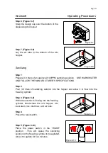
 

Step 6 (Figure 6-7)


Snap the design cap over the bottom of the 
dispensing door spout. 


Step 7 (Figure 6-8)


Lay  the  air  tube  in  the  bottom  of  the  mix 
hopper. 


Sanitizing 

 
Step 1


Prepare 3.8 liters of an approved 100PPM sanitizing solution.    USE WARM WATER 
AND FOLLOW THE MANUFACTURER’S SPECIFICATIONS. 

 
Step 2 

Pour  3.8  liters  of  sanitizing  solution  into  the  hopper  and  allow  it  to  flow  into  the 
freezing cylinder. 

 
Step 3 (Figure 6-9) 

While the solution is flowing into the freezing 
cylinder,  brush-clean  the  mix  hopper,  mix 
level stem, mix inlet hole, and air tube. 

 
Step 4 

Press the reset switch. 


Step 5 (Figure 6-10) 

Place  the  power  switch  in  the  “WASH” 
position.    This  will  cause  the  sanitizing 
solution in the freezing cylinder to be agitated.   
Allow it to agitate for five minutes. 

Figure 6-7 

Figure 6-8 

Figure 6-9 

Figure 6-10 

Содержание T15

Страница 1: ...ring are as follows 1 Be sure the freezer is electrical disconnected 2 Remove the appropriate panel and locate the small electrical box at the base of the freezer 3 Remove the factory installed cord and strain relief bushing 4 Route incoming permanent wiring through hole in base pan 5 Connect two power supply leads Attach ground earth wire to the grounding lug inside the electrical box 6 Be sure t...

Страница 2: ...d or assembly available from the manufacturer or its service agent MIX INFORMATION The hygiene ice cream powder is required to be used for frozen production Mix can vary considerably from one manufacturer to another Differences in the type of ingredients quality and quantity all have a different bearing on the finished frozen product A change in freezer performance that cannot be explained by a te...

Страница 3: ...may result in electrocution Contact your local authorized Distributor for service 5 DO NOT operate the freezer with larger fuses than specified on the freezer data label Failure to follow this instruction may result in electrocution or damage to he machine Consult your electrician 6 DO NOT operate the freezer unless all service panels and access doors are restrained with screws Failure to follow t...

Страница 4: ...ield T15000006 4 Top Panel T15020440 14 Drip Tray T15000007 5 Back Panel T15000002 15 Low Front Panel T15010002 6 Hopper T15020431 16 Panel A Front T15020301 7 Left Side Panel T15000003 17 Cylinder Evaporator T15020201 8 Drip Pan T15000004 18 Bolt T15020302 9 Leg Plastic T15010020 19 Indicator Light Mix Low T15070203 10 Top Front Panel T15070101 20 Right Side Panel T15000008 1 2 3 4 5 7 8 6 9 1 0 ...

Страница 5: ...020703 1 Seal O Ring 2 T15020710 1 Beat 3 T15020702 1 Front Bearing 4 T15020501 1 O Ring 5 T15020610 1 Dispensing Door 6 T15020504 2 O Ring 7 T15020503 1 Draw Valve 8 T15020505 1 Valve Lifter Arm 9 T15020506 1 O Ring 10 T15020507 1 Draw Valve Handle 11 T15020508 1 Design Cap 12 T15020509 2 Nut 1 2 3 4 5 6 7 8 9 10 11 12 ...

Страница 6: ...operating control Item Description Part No 1 Power Switch T1507C201 2 Spigot Switch T15070103 3 Mix Refrigeration Switch T1507C201 4 Reset Switch T1507C202 5 Indicator Light Mix Low T1507C203 6 Top Front Panel T15070101 The ON Position The WASH Position The Mix refrigeration Position The Standby Position The OFF Position 5 6 1 2 3 4 ...

Страница 7: ...hopper refrigeration system will start automatically When the Power and Mix refrigeration are both in ON position the separate hopper refrigeration system is also operation C Standby Position The Separate Hopper Temperature Retention System and the Cylinder Evaporator Refrigeration System are standard features The Separate Hopper Temperature Retention System incorporates the use of a separate smal...

Страница 8: ...h button switch Place the power switch in the WASH position and observe the freezer s performance place the power switch and the mix refrigeration switch in the ON position E Indicator Light Mix Low A mix level indicating light is located at the front of the machine When the light is on it indicates that the mix hopper has a low supply of mix and should be refilled as soon as possible Always maint...

Страница 9: ...the hopper There are close relations between hardness setting up and environment temperature producing the finished product actually Assembly Note When lubrication parts use an approved food grade lubricant Step 1 Install the beater assembly 1 Install the beater seal to the beater Figure 6 1 2 Insert the beater assembly through the rear shell bearing at the back of the freezing cylinder and engage...

Страница 10: ...sing door from the bottom Note The draw valve is installed correctly when the slotted opening in the draw valve is visible through the window of the dispensing door Step 5 Install the draw valve handle Figure 6 6 Insert the valve lifter arm through the slotted opening in the draw valve and align the other end with the cross holes of the dispensing door Hint The valve lifter arm may be aligned with...

Страница 11: ...FICATIONS Step 2 Pour 3 8 liters of sanitizing solution into the hopper and allow it to flow into the freezing cylinder Step 3 Figure 6 9 While the solution is flowing into the freezing cylinder brush clean the mix hopper mix level stem mix inlet hole and air tube Step 4 Press the reset switch Step 5 Figure 6 10 Place the power switch in the WASH position This will cause the sanitizing solution in...

Страница 12: ...FRESH mix and allow it to flow into the freezing cylinder This will force out any remaining sanitizing solution When full strength mix is flowing from the door spout lower the draw valve Note Use only fresh mix when priming the freeze Step 2 When the mix has stopped bubbling down into the freezing cylinder install the air tube in the mix inlet hole Steps 3 Figure 5 2 5 3 Place the power switch and...

Страница 13: ...raise the draw valve When all the product stops flowing from the door spout lower the draw valve and place the power switch in the OFF position If local health codes permit empty the rerun into a sanitized stainless steel rerun can Cover the container and place it in the walk in cooler Rinsing Step 1 Pour one 3 8 liters of cool clean water into the mix hopper With the brushes scrub the mix hopper ...

Страница 14: ...eezing cylinder to agitate Step 5 Place an empty pail beneath the door spout and raise the draw valve Draw off all the cleaning solution When the solution stops flowing from the door spout lower the draw valve and place the power switch in the OFF position Disassembly Step 1 BE SURE THE POWER SWITCH IS IN THE OFF POSITION Step 2 Remove the hand screws and the dispensing door Remove the beater asse...

Страница 15: ...om the dispensing door remove the design cap draw valve handle valve lifter arm and draw valve Remove all O rings Step 4 Remove the large O rings and front bearing from the back of the dispensing door Step 5 Return to the freezer with a small amount of cleaning solution With the black bristle brush brush clean the rear shell bearing at the back of the freezing cylinder Step 6 Remove the rear drip ...

Страница 16: ...stment switch is located under the decorative panel Remove the decorative panel find a P C board On the left top side of P C board find a 6 position switch P C Board 6 Position Switch Step 3 The hardest level is switch 1 ON and the softest level is switch 6 ON Adjust the hardness of ice cream product change the 6 position switch setting HARDER SOFTER DIP SWITCH 2 IS ON ...

Страница 17: ...stle brush to thoroughly clean the rear of the freezing cylinder Be sure to have a generous amount of cleaning solution on the brush 5 IF LOCAL HEALTH CODES PERMIT THE USE OF RERUN make sure the mix rerun is stored in a sanitized covered stainless steel container and is used the following day DO NOT prime the machine with rerun When using rerun skim off the foam and discard Mix the rerun with fres...

Страница 18: ...ly maybe the belt is worn torn or fit too loosely Dispose of the belt and replace with new ones 6 Follow all lubricating procedures as outlined in ASSEMBLY 7 This machine is air cooled check the condenser for an accumulation of dirt and lint A dirty condenser will reduce the efficiency and capacity of the machine Condensers should be cleaned monthly with a soft brush Never use screwdrivers or othe...

Страница 19: ...switch e Place the circuit breaker in the ON position or replace the fuse Press the reset switch f See Operating Procedures for proper installation g Stop drawing product and allow the unit to recover 7 8 1 8 1 9 13 2 The machine will not operate in the ON mode a The unit is unplugged b The circuit breaker is tripped or the fuse is blown c The beater motor overload causing a loss of power to the p...

Страница 20: ... shaft properly 9 9 7 The draw valve is leaking a Incorrect lubricant was used b A worn or defective O ring are on the draw valve c Inadequate lubricant of draw valve a Use food lubricant b Replace the O rings every 3 months c Lubricate the draw valve shaft properly 9 9 9 8 Product is not feeding into the freezing cylinder a The mix level is inadequate in the mix hopper b The mix inlet hole is fro...

Страница 21: ...n Compressor M3 T15500C03 1 Main Fan Motor M4 T15500M11 1 Mix Compressor M5 T15500M12 1 Mix Fan Motor JR T15500M13 1 Thermal Overload Relay WK1 T15000001 1 Thermostat of hopper WK2 T15000002 1 Thermostat of evaporator KM1 T15000002 1 Contactor of Motor KM2 T15000003 1 Contactor of Compressor Q1 T1507C201 1 Power Switch Q2 T1507C201 1 Mix Refrigeration Switch S1 T1507C202 1 Reset Button S2 T1507C10...

Страница 22: ... KM2 PC w0 w1 w0 w1 w4 w7 w11 w19 w20 w8 w4 w7 w11 w19 w8 w31 w31 _ 1 2 3 WK2 W20 S1 S2 º Q1 º T1 º D º KM1 KM2 º M1 º M2 º M3 º M4 º M5 º T2 º PC º 1 2 3 WK1 L N GND WK1 WK2 º Electrial Drawing Reset Button Spigot Switch Power Switch Mix Refrigeration Switch Transformer Indicator Light Mix Low Contactor Drive Motor Main Compressor Main Fan Motor Mix Compressor Mix Fan Motor Inductance Control Boa...

Отзывы: