6. DOCK LEVELER INSTALLATION INSTRUCTIONS
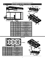
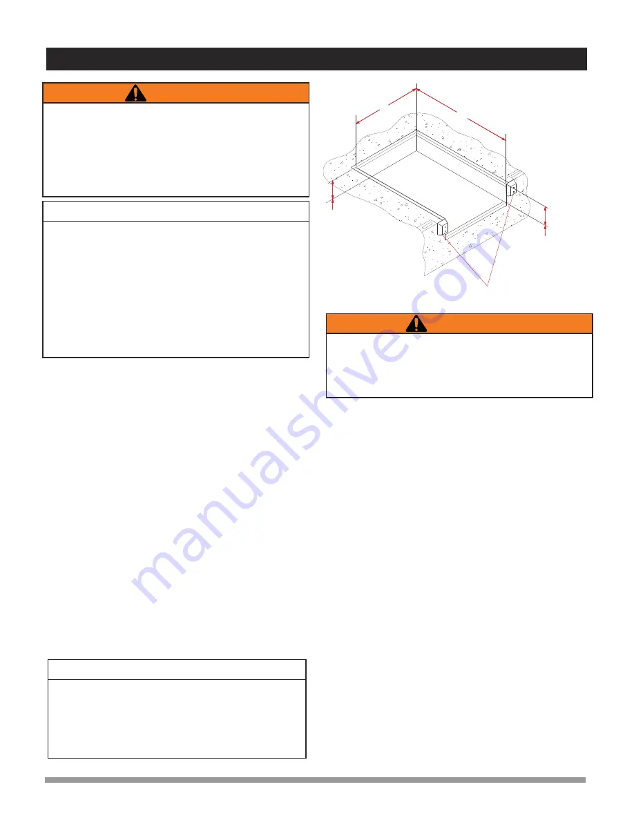
LENGTH
PIT MUST BE
KEPT SQUARE
WIDTH
DOCK BUMPERS
Typically
24” (609mm).
Typically
23 1/2”(595mm)
Figure 1 : Pit Layout - Typical (Six piece curb angle shown)
!
IMPORTANT
!
Do not install, operate and/or service this leveler until you
have read and understood all of the safety information
and instructions contained herein and on the leveler.
Do not work under or around leveler being installed
without first placing adequate barriers to positively
prevent vehicle traffic from entering the work area.
Keep hands and feet clear of dock leveler pinch points.
!
The information below is crucial to proper installation:
Pit Curb Angles
A. Must be level side-to-side and front-to-back.
B. Must be square at both rear corners.
C. Side curb angles must be parallel to each other.
D. Finished floor to be flush with top surface of curb angle.
The leveler must be welded to a firmly embedded steel or other
dock steel as described in the installation instructions.
Do not attempt to use only bolts or anchors, to attach the dock
leveler to the concrete.
1.
Prior to installation, clean pit thoroughly and verify that all
dimensions are in accordance with manufacturer specifica-
tions.
2.
Measure height of rear corners of dock leveler, bottom of
frame to top of deck plate, typically 23” (585mm). Measure
depth of pit at both rear corners where rear bottom corners of
frame will be positioned. Locate and place suitable shims (not
supplied) in pit corners to produce a depth to match frame
height.
3.
Measure height of dock leveler front corners, bottom of frame
to top of deck plate, typically 23-1/2” (595mm). Measure
depth of pit at both front corners where front bottom corners of
frame will be positioned. Locate and place suitable shims (not
supplied) at both front corners to produce a depth to match
frame height. See Figure 1.
!
4.
Using slings that are rated for a minimum capacity of 2,000 lbs
(1,000 kg), carefully sling the dock leveler into place squarely
above the pit and lower it gently onto the pre-located shims.
Position the leveler to best suit the pit and the dock face.
Space between the sides of the deck and sides of the pit
should be equal.
Use caution when lifting or moving the leveler. Do not attempt
to lift without suitable hoisting equipment capable of lifting as
much as 2,000 lbs (1,000 kg). Follow all hoisting safety require-
ments.
5.
If the rear beam does not line up squarely with the rear curb
angle, use 3” x 6” (75mm x 150mm) shims of suitable
thickness to fully support top rear and bottom rear of rear
beam at weld areas.
6.
Remove and discard the shipping bolt from the front of the lip
plate.
7.
There are two options for raising the deck to enable access to
the blower motor for electrical hookup.
A) Prepare to hook up electrical wires to establish a temporary
electrical hookup to enable the deck to be raised.
B) Use sling brackets and chains to raise the deck and allow
access to the blower motor for electrical hookup.
8.
Use the maintenance strut to engage the headboard and lip
and hold the deck and lip in the raised, extended position.
9.
Complete proper electrical hookup to blower motor.
10.
Locate and place adequate and appropriate spacer shims to
completely fill the space between the curb angle and frame at
the following locations under the front frame:
A) Under the maintenance strut base mounting bracket
between the curb angle and frame.
B) Under the lip keeper brackets (one at each side of frame)
between the curb angle and the frame.
C) Under the center point of the front frame between the curb
angle and the frame.
11.
After all electrical connections have been properly completed,
press and hold the UP ‘I’ button until the deck has raised high
enough to allow successful disengagement of the
maintenance strut. Release the button and allow the deck to
lower to the stored position. Ensure that the lip is parked
inside the lip keepers.
12.
Adjust the height of all front shims as required to level the front
sides of the deck with the pit curb angles. Tack-weld the front
shims together as well as to the dock leveler frame and the pit
curb angle.
IMPORTANT
It is important that the shims fill the space between the
bottom edge of the back beam and face of the curb angle, as
well as behind each hinge lug on the top edge. Confirm that
the top of the back beam is flush with the top surface of the
rear curb angle, and then finish weld back beam to curb
angle.
U-SERIES AIRBAG DOCK LEVELER with SINGLE PUSH BUTTON CONTROLS
6


