4
ZFMSM
Instruction Manual
One Jake Brown Road
Old Bridge, NJ 08857-1000 USA
(800) 523-6049 • (732) 679-4000 • FAX: (732) 679-4353
www.blondertongue.com
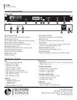
Specifications (Typical)
RF
Frequency Range: 88-108 MHz
Frequency Step: 100 kHz
Output Level: +35 dBmV
Output Level Adjust: 10 dB
Frequency Stability: ±10 kHz
Audio Input Level: 0.2 to 2.0 V p-p
Audio Frequency Range: 30 Hz to 15 kHz
Audio S/N Ratio: >60 dB
Audio Seperation: >30 dB
General
Power Requirements
Voltage: 120, ±10% VAC
Frequency: 60 Hz
Power: 10 W
Temperature Range: 0 to +50 °C
Mechanical
Dimensions (W x H x D): 19.0 x 1.75 x 3.01 in.; 483 x 44 x 76 mm
Weight: 5 lbs.; 2.1 kg
Controls (Top Panel)
Audio Input: L/R "F" Type Female
RF Output: "F" Type Female
Test Port: "F" Type Female
Connectors (Top Panel)
Frequency Setting: Up/Down Control
Aural Modulation Adj: Control
RF Output Level: Control
Indicators
Power ON: LED, Red
Frequency Display: 4 Digit LED Screen
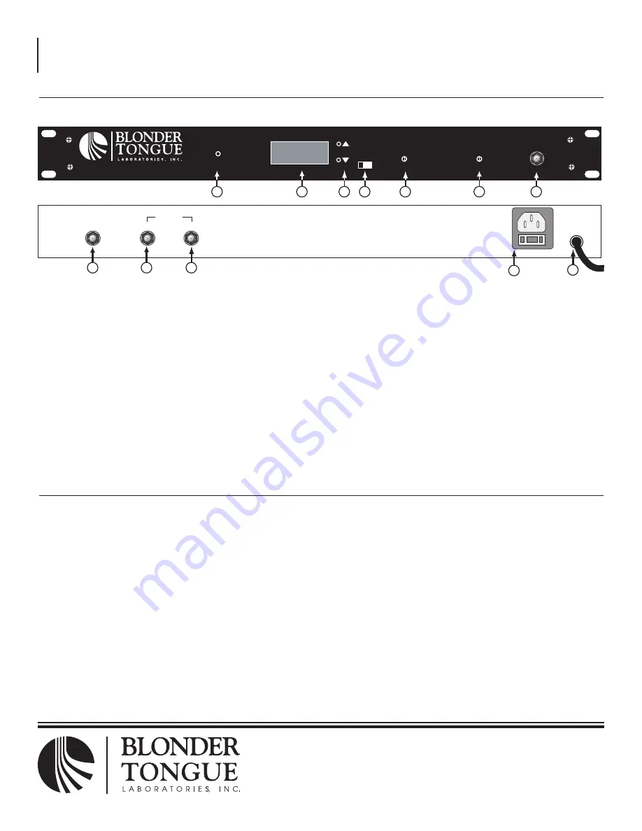
Controls and Connections
[1]
POWER INDICATOR:
LED illuminates to indicate presence of power
[2]
FREQUENCY DISPLAY:
Seven segment display indicates FM frequency setting
[3]
FREQUENCY SELECT CONTROLS:
Push buttons used to select desired frequency
[4]
MONO/STEREO SWITCH:
Slide switch used to select mono or stereo modes
[5]
AUDIO MODULATION LEvEL:
Adjusts aural carrier modulation
[6]
RF OUTPUT LEvEL:
Adjusts RF output
[7]
-20 dB TEST POINT:
Externally accessible for in-service testing
[8]
RF OUTPUT:
RF signal is connected to distribution system
[9]
AUDIO IN:
Connect a 1 v p-p (2 v p-p max.) mono or stereo signal
source from a satellite receiver or vCR
[10]
CONvENIENCE OUTLET:
Allows looping of power between units
[11]
POWER CORD:
Three prong power cord connects to a 120 vAC outlet
ZFMSM
AGILE FM MODULATOR
1
2
3
FREQ.
4
5
6
7
100.3
M S
AUDIO
MODULATION
ADJ.
R.F.
OUTPUT
LEVEL
TEST
POINT
-20 dB
POWER
RF OUT
AUDIO IN
R L
600W MAX.
120 VAC
60 Hz, 10 W
8
9
10
11
12
FRONT PANEL
REAR PANEL


