8
BTY-UHF-BB
Instruction Manual
Preparation for Installation
1. Items Required (but not supplied)
1 “F” Connector (male)
1 Tube silicon grease
1 Roll Electric tape
2. Tools Required
1 each nut driver: 1⁄4”, 7/16”, 9/16”, 5/8”
1 each open end wrench: 7/16”, 9/16”, 5/8
3. Check hardware and tools to ensure that all material is on hand
4. Read all instructions before starting assembly/installation
Installation Procedure
Mast Mounting
1.
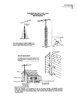
Mount the antenna on the mast (“F” connector down). Use the hardware contained in Bag #1 (U Bolt, Back
Plate, etc.) as shown in Fig. 1. The antenna can be attached on either the right or the left side of the mast, but
the U Bolt should be inserted through the upper boom.
2.
Coat the cable connection with silicone grease before covering it with the weatherboot supplied. You may find
it more convenient to attach the coaxial cable before mounting the antenna.
3.
Securely lash the downlead to the mast. For best results the coax should be fastened to the antenna boom as
shown in Fig. 2, with the nylon ties supplied.
Mounting to VHF Broadband Antenna
(Coupling the 4875 BTY-UHF-BB Antenna to the 4874 BTY-LP-BB (VHF) Antenna to make a single Broadband
All-Channel UHF/VHF Antenna).
NOTE: Requires Optional Mounting Kit BTY-UVMK Stock No. 4882
1.
Unpack and assemble the VHF Antenna (4874) according to the instructions included with it. HOWEVER, do not
secure the forward element (#12) of the lower boom with the clamp and screw at this time, also the 75 Ohm
coaxial cable MUST extend at least 30 inches out of the lower boom front. This length will be needed to connect
the UHF Antenna.
If the VHF Antenna is already completely assembled, remove the clamp and #8 x 1-3/4" screw from the lower
forward (#12) element (save the screw for later use) and extend the coaxial cable 30 inches, as above.
2.
Unpack the assembled UHF antenna. Open the option A1 Mounting Kit (BTY-UVMK, Stock No. 4882) containing
the upper and lower boom couplers, spacers, etc.)
3.
Mount the Lower Boom Coupler to the bottom of the lower UHF boom with (2) each 1/4 - 20 Bolts, Lockwashers
and Nuts, using the spacers, as shown in Fig. 3. Mount the Upper Boom Coupler Plate to the top of the upper
UHF boom with (4) #6 x 3/8” Screws as shown in Fig. 4.
4.
Move the back of the UHF Antenna (with the couplers attached, step 3, above) into the front of the VHF Antenna,
making sure the coaxial cable exits the VHF Antenna in the gap between the open front end of its lower boom
and the smaller UHF boom. Using the Lower Boom Coupler in place of the bottom element clamp, insert the #8
x 1-3/4” screw and secure the forward (#12) VHF Antenna element using the clamp-nut (as for the other VHF
elements) on top. See Fig. 3.
5.
Insert (4) #6 x 3/8” screws on the bottom and sides of the lower boom coupler. Tighten all hardware firmly.
Insert (4) #6 x 3/8” screws into the top of the upper boom coupler and tighten firmly.
6.
Place the 75 Ohm coaxial cable from the VHF Antenna along the lower UHF Antenna boom as shown in Fig. 5
and secure with the cable ties supplied.
7.
Slip the weatherboot onto the coax, attach an “F” connector, then screw it to the UHF antenna’s jack. Coat the
connection liberally with the silicone grease before covering it with the weatherboot.
Содержание BTY-UHF-BB
Страница 3: ...3 BTY UHF BB Instruction Manual ...
Страница 4: ...4 BTY UHF BB Instruction Manual ...
Страница 5: ...5 BTY UHF BB Instruction Manual ...
Страница 6: ...6 BTY UHF BB Instruction Manual ...
Страница 9: ...9 BTY UHF BB Instruction Manual ...
Страница 10: ...10 BTY UHF BB Instruction Manual ...
Страница 12: ......


