background image

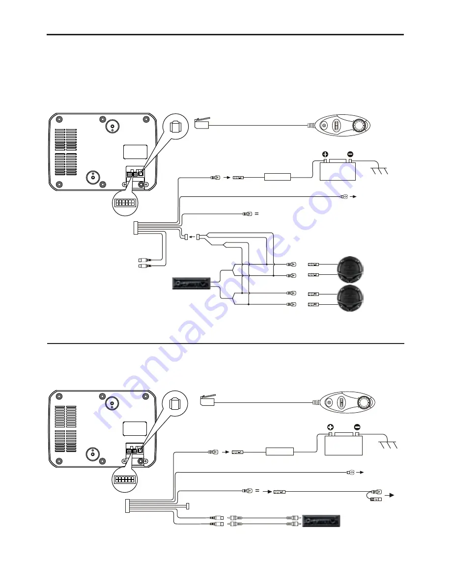
WIRING DIAGRAM


Diagram 1 

(High Level Input)

Diagram 2 

(Low Level Input)

REMOTE CONTROL

YELLOW WIRE

BLUE/WHITE WIRE

NOT IN USE IN THIS TYPE OF INSTALLATION

NOT IN USE IN THIS

TYPE OF INSTALLATION

GREY/BLACK (-) & GREY WIRE (+)

SPEAKER RIGHT CHANNEL
OUTPUT WIRE

SPEAKER LEFT CHANNEL OUTPUT WIRE

WHITE/BLACK (-) &
WHITE WIRE (+)

FUSE

10A

BATTERY

12V

CONNECT BLACK WIRE (-) TO THE CHASSIS OF THE VEHICLE

CHASSIS GROUND

Select one Diagram 1 or Diagram 2 for installation.

Avoid audio interference by using one audio inputs only.

REMOTE CONTROL

YELLOW WIRE

BLUE/WHITE WIRE

RCA SIGNAL WIRE

AUDIO DEVICE CONTROL WIRE

CONNECT BLACK WIRE (-) TO THE CHASSIS OF THE VEHICLE

FUSE

10A

BATTERY

12V

CHASSIS GROUND

Содержание GTr 96 A

Страница 1: ...GTr 96 A ACTIVE SUBWOOFER Enjo Operating and Installation Instructions yit ...

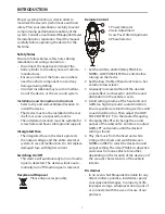
Страница 2: ...l automatically turn on if audio signal is detected The device will also auto matically turn off if audio signal is received Please dispose responsibly Remote Control 1 2 3 4 5 6 Disclaimer 1 Power Indicator 2 Gain Adjustment 3 Low Pass Filter Adjustment 4 Phase Selector Set the GAIN to 200mV Min PHASE to NORM LOW PASS FILTER to Center before turning on the device Set the Bass Treble of head unit ...

Страница 3: ...TION USA CANADA Product not intended for sale in the United States and Canada If purchased in the U S or Canada this product is purchased as is No warranty express or implied is provided in the U S and Canada 2 ...

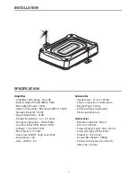
Страница 4: ...50Hz Low Pass Filter LPF 83Hz 150Hz Voltage 14 4V 10V 16V Phase Switch 0 180 Automatic On Off High Level Only Fuse Rating 10A Gain 200mV 6V Speaker Size 214 5 x 135mm Cone Composition Aluminium Magnet Type Ferrite Enclosure Housing Material Plastic Aluminium Remote Controller Wired DC Cord 350mm Screws Parker Type M4 x 20 mm Screws M Type M6 x 8mm Bracket A 72 x 40mm Overall Net Weight 2 89kg Encl...

Страница 5: ...NEL OUTPUT WIRE SPEAKER LEFT CHANNEL OUTPUT WIRE WHITE BLACK WHITE WIRE FUSE 10A BATTERY 12V CONNECT BLACK WIRE TO THE CHASSIS OF THE VEHICLE CHASSIS GROUND Select one Diagram 1 or Diagram 2 for installation Avoid audio interference by using one audio inputs only REMOTE CONTROL YELLOW WIRE BLUE WHITE WIRE RCA SIGNAL WIRE AUDIO DEVICE CONTROL WIRE CONNECT BLACK WIRE TO THE CHASSIS OF THE VEHICLE FU...

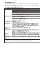
Страница 6: ...If yes examine if the cables are correctly connected and if the cables and radio are in good condition Repair or replace if the cables or the radio are not in good condition Ensure RCA connections are properly connected Ensure input level of the device matches the signal level of the head unit Always set the input level to the lowest Examine if crossover frequency is set correctly Examine if speak...

Страница 7: ...Designed and engineered by Blaupunkt ...

Отзывы: