background image

Before Installing and Testing (continued)

Transport Lock Screws

The mechanism in the CD changer is “locked” into place during
shipment by three transport screws. Be sure to remove the screws prior
to testing the system and installation.

To keep dust out of the unit, which could cause a malfunction, place the

enclosed seals over the screw holes after the Transport Lock Screws
have been removed.

Reset Button

A Reset Button is located on the front panel of the Commander
and must be activated with a pen tip or other thin object, as it is

recessed to prevent accidental engagement. Press the Reset
Button under the following circumstances:

1. After connections have been made for initial testing.

2. After installation, when all wiring is completed.
3. If abnormal disc operation is encountered, the Reset Button

should be pressed to clear the system to return to normal
operation.

4. After disconnecting and reconnecting the car battery, etc.


ID (Identity) Switch for 2nd CD Changer

To connect a second CDC-RF 6 changer, you

must use Blaupunkt’s CDC-RF BRIDGE,

which is sold separately. When an
additional CD changer has been connected

using this unit, the ID switch is used to
indicate the number of each respective
changer unit.

The ID switch is initially set to “1” when
shipped.

When only one changer is connected, the
switch should be set to   

When two changers are connected, one
of the unit’s switches should be set to “2”
using a ballpoint pen or similar fine-tipped

1

2

C D

1 st unit

2

C D

Setting the Radio Frequency
You 

must select and test the radio frequency that the changer will use before

you mount the FM Modulator.

Set the radio frequency setting to 89.1 using the switch on the back of the
FM Modulator. Test the operation of the changer. (See page 15) If a clear
signal cannot be obtained on 89.1 MHz, change the position of the
frequency-select switch to 88.7.

The radio sensitivity is slightly reduced when the FM Modulator is connected.

2nd unit (additional changer unit)

Содержание CDC RF6

Страница 1: ...e Radio Changeur de CD modulateur FM 6 disques Cambiador de Discos Compactos Para 6 Discos y Modulador de FM Para Uso con Cualquier Radio FM de Vehiculo Cambiador CD para 6 discos corn Modulador FM para uso corn qualquer Rtidio FM de Autombvel BLAUPUNKT Bosch Group ...

Страница 2: ...equipment in order to comply with limits for a digital device pursuant to Sub part B of Part 15 of the FCC rules l Because the laser beam used in this compact disc changer is harmful to the eyes do not attempt to disassemble the cabinet Refer servicing to qualified personnel only l You are cautioned that any changes or modifications not expressly approved in this manual could void your warranty an...

Страница 3: ...iscos Compactos 4 5 Ubicacion de 10s Controles 46 lnstrucciones de Operation 47 Cambio a un Segundo Cambiador 48 Cambio a Ejecucion de Radio o de Cinta 48 Guia de Detection de Problemas 49 Codigo de Errores 50 Antes de instalar e operar esta unidade por favor leia este manual minuciosamente e guarde o para futura referencia Sommaire Archive du proprietaire 19 Avertissement de la FCC 19 Caracterist...

Страница 4: ... ground systems The unit cannot be used on 24 volt or positive ground systems l If your vehicle was parked in direct sunlight resulting in a considerable rise in temperature inside the vehicle allow the unit to cool off before operating your unit The unit may not operate correctly in extremely hot or cold temperatures The unit is equipped with a built in self protection circuit When the temperatur...

Страница 5: ...g and reconnecting the car battery etc ID Identity Switch for 2nd CD Changer To connect a second CDC RF 6 changer you must use Blaupunkt s CDC RF BRIDGE which is sold separately When an additional CD changer has been connected using this unit the ID switch is used to indicate the number of each respective changer unit l The ID switch is initially set to 1 when shipped l When only one changer is co...

Страница 6: ...car that is equipped with an on board drive or navigation computer do not disconnect the battery cable If the cable is disconnected the computer memory may be lost Under these conditions use extra caution to avoid causing a short circuit during installation l Connect leads according to the wiring diagram l Connect the yellow lead to a constant source of power which has passed through the vehicle s...

Страница 7: ...ipment in or under the trunk l For a safe and secure installation be sure to use only the supplied mounting hardware l Press the reset button after completing the electrical connections and installation The reset button is located on the front of the Commander See page 5 l If you have any questions or problems concerning your unit that are not covered in this manual please contact your Blaupunkt d...

Страница 8: ...ackets L and R to their respective brackets 5 using tha hexagonal bolts M6 x 20 and the hexagonal nuts M6 where to attach the unit l Stick the supplied double sided tape to the bottom of the brackets B and peel off the paper backing l Affix the unit to the floor by pressing in place take off the changer l Return the carpet to its original position allowing the bolts to protrude through to attach t...

Страница 9: ...rpet and determine where to attach the unit l Stick the suoolied double sided tape to the bottoi of the brackets B and peel off the paper backing l Affix the unit to the floor by pressing in place Ant Vibration Cs 4 l Using a knife cut X s in the carpet directly above the brackets B bolts l Return the carpet to its original position allowing the bolts to protrude through Q l Remove the hexagonal n...

Страница 10: ...ckets B using the hexagonal bolts M6 x 20 and the hexagonal nuts M6 where to attach the unit l Stick the supplied double sided tape to the bottom of the brackets B and peel off the paper backing l Affix the unit to the floor by pressing in place l Remove the hexagonal nuts and take off the changer directly above the brackets B bolts l Return the carpet to its original position allowing the bolts t...

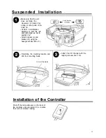
Страница 11: ...th the left and right sides are set to position HI l Attach bracket L and bracket R using the hexagonal bolts M5 x 8 0l Determine the mounting location and drill four mounting holes 3 6 mm Diameter Q l Attach the CD changer with the tapping screws M5 x 12 Installation of the Controller Peel off the removable seal on the back of the controller unit and install it in a location that will not obstruc...

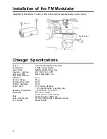
Страница 12: ...gnal to Noise Ratio Channel Separation Current Drain Operating Temperature Dimensions Mass Power Requirement Part Number Compact disc digital audio system 1 Bit 8 X Oversampling GaALAs Double Hetero Type 20 l 5 000 Hz 3 dB Below Measurable limit 0 1 95 dB 90 dB 75 dB 0 4 A During playback 1 O A During loading or ejecting a disc 10 to50 C 14 to122 F 25Ox64x178mm 9 7 8 x 2 l 2 x 7 in W x H x D Appro...

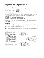
Страница 13: ...cs should be put back in their cases after use to avoid serious scratches that could cause the sound to skip Cleaning Discs Before playing remove fingerprints and dust the disc with a compact disc cleaning cloth Wipe the disc from the center of the disc to the outer edge of the disc Do not use solvents such as benzine thinner commercially available cleaners or anti static spray intended for analog...

Страница 14: ...ine Note Be sure to close the door after inserting or removing the magazine If dust or dirt enters the changer it may cause a malfunction Remove the magazine from the unit between uses during hot weather and when the CD changer is not used for long periods of time Location of Controls 7 a TRACK SELECT REVIEW CUE CDC RF6 COMMANDER 6 5 2 1 Play Pause Button Press to turn unit on to temporarily pause...

Страница 15: ...y begins with the first track on the disc When the last track on the last disc in the CD magazine is finished the first disc is automatically selected and play begins with the first track on the disc Moving To Another Track l To go to the next track press and release the H Control 3 l To go back to the beginning of the track being played press and release the w Control 3 l Press these controls rep...

Страница 16: ...uttQn 7 is pressed SCAN appears and the first 10 seconds of each track on the selected disc are played in order To cancel press it again Disc Scan When the Scan Button 7 is pressed for two seconds or more DISC and SCN appears and the first 10 seconds of each track on each disc are played in order To cancel press it again Switching TO A Second CD Changer Ifconnected If the CDC RF BRIDGE sold separa...

Страница 17: ...acing up Printed side should face down Noise is heard during playback or sound is intermittent Large scratches on disc or warped Compare sound with another disc If disc sound from second disc is acceptable first disc is defective Extemely dirty disc Clean disc Transit Screws still in place Remove 3 screws on bottom of unit and try again Anti Vibration Switch set in wrong position Set the Anti Vibr...

Страница 18: ...on Disc loaded with print facing up or disc is dirty Temperature inside car too hot Remedy Consult with dealer Load disc properly Clean disc Allow the car to cool Then press the Play Pause Button I m I Magazine has not been installed Install magazine g 1 I 11 E No discs in magazine El 1 5 Load discs into magazine I I I E No discs in slot No 2 Load discs into slot No 2 18 ...

Страница 19: ... BLAUPUNKT Bosch Group Robert Bosch Corporation Sales Group Mobile Communications Division 2800 South 25th Avenue Broadview Illinois 60153 0 Robert Bosch Corporation Printed in Japan 1 RAGPlOA71600 ...

Отзывы: