background image

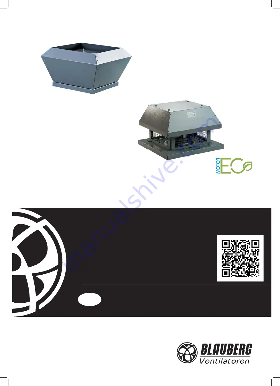
Tower-V

Tower-H

Tower-V EC

Tower-H EC

CENTRIFUGAL ROOF FAN

OPERATION MANUAL

EN

Содержание Tower-H 220 2E

Страница 1: ...Tower V Tower H Tower V EC Tower H EC CENTRIFUGAL ROOF FAN OPERATION MANUAL EN...

Страница 2: ...fety regulations 3 Transportation and storage regulations 3 Manufacturer s warranty 3 Design 4 Delivery set 5 Technical data 5 Mounting and operation guidelines 7 Connection to power mains 9 Technical...

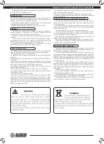
Страница 3: ...quirements to ensure a trouble free and long service life of the unit TRANSPORTATION AND STORAGE REGULATIONS Transportation of the unit is allowed by any vehicle provided the unit is transported in th...

Страница 4: ...h terminals leaded outside for connection to external protecting controls The thermal switch terminal leads are designed for connection to respective circuit of the terminal block overload relay or re...

Страница 5: ...sure level at 3 m distance dB A 53 46 53 52 52 Max transported air temperature C 65 50 70 80 60 Ingress protection rating IP X4 IP X4 IP X4 IP X4 IP X4 Parameters Tower V 450 4 Tower H 450 4 Tower V 4...

Страница 6: ...4 668 535 872 30 Tower V 400 4D 438 420 598 450 783 27 5 Tower V 450 4D 438 454 668 535 872 30 Tower V 500 6 438 454 668 535 872 33 8 Tower V EC 250 285 320 435 330 528 16 Tower V EC 280 285 327 435 3...

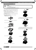
Страница 7: ...ting sequence for Tower V EC 1 Cut off power supply QF 2 Mark and drill the holes for the dowels above the ventilation shaft 3 Unscrew 8 bolts that fix the protecting housing 4 Remove the protecting h...

Страница 8: ...e casing of the fan pan Install the pan of the fan over the ventilation shaft and fix it using dowels 6 Route the electric cable through the electric lead in located in the base casing Install the bas...

Страница 9: ...t by a qualified electrician and after reading the operation manual The rated electrical parameters are stated on the rating plate Any tampering with the internal connections is prohibited and will vo...

Страница 10: ...verheating protection Connect the contact in series to power circuit of the magnetic starter coil KM1 that starts the motor after pressing the S1 button In case of the motor overheating the contact ge...

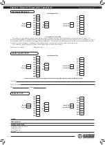
Страница 11: ...Terminal block Contact Purpose function KL3 OUT control signal output 0 10 V max 3 mA GND ground 0 10 V PWM Control input full resistance 100 kOhm 10 V external potentiometer power supply 10 V 10 max...

Страница 12: ...3 L QF N PE TW1 4 5 6 TW2 230 V 50 Hz KM1 S2 Off S1 On KM1 X1 400 V 50 Hz S2 Off S1 On L1 TW1 TW2 KM1 L2 L3 QF L1 L2 L3 N PE PE Fig 15 Fig 16 PC with the interface converter RS 486 Pressure sensor War...

Страница 13: ...inst liquid ingress 4 Assemble the fan in the reverse order after cleaning QF WARNING Cut power supply to the fan off by turning the automatic electric switch QF to OFF position prior to any maintenan...

Страница 14: ...the laws of the Member States relating to electromagnetic compatibility which relate to electrical appliances used in set voltage classes This certificate is issued following test carried out on samp...

Страница 15: ...___________________________________________ _______________________________________________________________________________________ ____________________________________________________________________...

Страница 16: ...www blaubergventilatoren de Tower H V v 4 7 EN...

Отзывы: