


12
www.blaubergventilatoren.de
KOMFORT EC S/SB
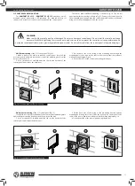
Connect the
KOMFORT EC S S11 / KOMFORT EC SB S11
units to single-
phase AC 230 V/50-60 Hz power mains using the power cord with the Euro
Plug, pre-wired at the factory. The unit must be grounded in compliance with
the valid electrical standards of the user country!
Connect the unit to the terminal block X1, located in the control unit, in
compliance with the external connections wiring diagram.
The unit has an
option of additional external controls connection to the X1 terminal block
(Fig. 17). The unit must be grounded in compliance with the valid electrical
standards of the user country!
Cut power supply to the unit off by turning the automatic electric switch
QF to OFF position prior to any operations.
Take steps to prevent activation of the automatic switch before fi nishing
all the operations.
QF
CONNECTION TO POWER MAINS
WARNING
Read the service instruction prior to any electric installations. Connection of the unit to power mains is allowed by a
qualifi ed electrician only.
The rated electrical parameters are stated on the rating plate. Any tampering with the internal connections is prohibited
and will void the warranty.
Connect the unit only to power mains with valid electric standards.
Follow the respective electric standards, safety rules (DIN VDE 0100), TAB der EVUs. The house cabling system must be
equipped with a magnetic trip automatic switch at the external input. The contact gap on all poles must be at least 3 mm (VDE
0700 T1 7.12.2 / EN 60335-1).
The automatic switch trip current must be not below the rated current consumption (ref. Table 1). Enable quick access to an
automatic switch installation place.
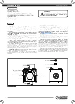
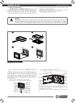
CONDENSATE DRAINAGE
The hole for the drain pipe is at the bottom of the unit. Remove the plug
from the hole, open the service panel and install the drain pipe from the
delivery set into the hole, then connect the drain pipe to the sewage system
using the KIT SFK 20x32 condensate drainage kit (available upon separate
order).
The condensate drainage system is designed for normal operation in
premises with air temperatures above 0 °C!
If the expected ambient air temperatures are below 0 °C the
condensate drainage system must be equipped with heat insulation and
pre-heating facilities.
WARNING
In case of several units mounting connect each unit to an individual U-trap.
Direct condensate drainage with no connection to the drain system is not allowed.
!
Fig. 16. Condensate drainage
min 3°
Drain hose
U-trap
Sewage system
Drain pipe


