BLAUBERG Ventilatoren Fresher 50 Скачать руководство пользователя страница 11

www.blaubergventilatoren.de

Fresher 50 (l) (m)

11

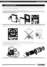
POWER OFF THE POWER SUPPLY PRIOR TO ANY OPERATIONS WITH THE UNIT.

THE UNIT MUST BE CONNECTED TO POWER SUPPLY BY A QUALIFIED ELECTRICIAN.

THE RATED ELECTRICAL PARAMETERS OF THE UNIT ARE GIVEN ON THE 

MANUFACTURER’S LABEL.

The ventilator is rated for connection to single-phase AC 100-240 V 50/60 Hz power mains.
Connect the ventilator to power mains through an automatic circuit breaker with magnetic trip integrated into the home wiring system. 
The tripping current of the circuit breaker is selected based on the electrical characteristics shown on the label of the fan casing. For 
electric installations use insulated, durable and heat-resistant conductors (cables, wires) with the minimum cross section of 0.5 up to 
0.75 mm2 for a power cable and 0.25 mm2 for signal cables.
The cable cross-section is given for reference only. The actual conductor cross-section selection must be based on its type, the maximum 
permissible heating, insulation, length and installation method. Use copper wires for all the electric connections!
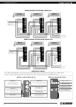
Connect the ventilator to power mains in compliance with the wiring diagram.

EXTERNAL CONNECTIONS DIAGRAM

The ventilator design enables connecting any external controls 
with a normally opened contact (NO-contact), such as an external 
CO2 sensor, humidity sensor, relay switch, etc.
When the normally open contact of the external device is closed, 
the ventilator goes to a maximum speed.
The ventilators can be connected in series and in parallel with a 
central control by the master ventilator.
In case of in series or in parallel connection of several ventilators 
power is supplied either from a previous ventilator or from power 
mains.

N

L

N

L

In

Gnd

NO1
NO2

+12V

Gnd

Out

QF*

L (~)
N (~)

Control signal output

to the next ventilator

Power

АС 100-240V 

50/60 Hz

Power to the 

next ventilator

Normally open contact

of the external device

(relay sensor)

Control signal input from 

the previous ventilator

CONNECTION TO POWER MAINS

Содержание Fresher 50

Страница 1: ...Single room through the wall ventilator USER S MANUAL EN Fresher 50...

Страница 2: ...nless they have been given supervision or instruction concerning use of the unit by a person responsible for their safety Children should be supervised to ensure that they do not play with the unit Th...

Страница 3: ...ck the unit for any visible damage of the impeller the casing and the grille before starting installation The casing internals must be free of any foreign objects that can damage the impeller blades W...

Страница 4: ...for wall flush mounting Name Number Indoor assembly unit of the ventilator 1 pc Air duct 1 pc Sound absorbing material 1 pc Cartridge assembly 1 pc Outer ventilation hood 1 pc Remote control optional...

Страница 5: ...The ventilator design is regularly improved so some models may slightly differ from those ones described herein The air duct length depends on the unit model refer to the Designation Key The supplied...

Страница 6: ...and other objects to the ventilator Front part of the indoor unit with a face panel Fulfils the decorative function The design enables to shut off the air duct in case of an extended downtime of the...

Страница 7: ...ers are opened and let the air flow freely through the ventilator The automatic shutters are closed for 2 minutes at the ventilator shut down WARNING In case of supplying power to the ventilator when...

Страница 8: ...power cable and other required cables 180 7 min 300 min 12 min 300 min 12 min 300 min 12 A A A A 2 Install the air duct in the wall in such a way so it protrudes from the wall surface for maximum 3 m...

Страница 9: ...ening on the master plate 4 Unlatch and detach the front part of the indoor unit from its back part While installing the front panel the thermal actuator rod must be in low position 5 Fix the back par...

Страница 10: ...hermal actuator rod must be in lower position when installing the front panel as shown in the figure in Section 4 on page 9 9 Insert the sound absorbing layer into the air duct from the outside Roll t...

Страница 11: ...uctor cross section selection must be based on its type the maximum permissible heating insulation length and installation method Use copper wires for all the electric connections Connect the ventilat...

Страница 12: ...r Alarm Master Speed Master indicator Indicator of the first ventilator in the group Alarm indicator In case of the motor jam the Alarm indicator starts blinking and the ventilator stops All the venti...

Страница 13: ...tor requiring filter replacement blinks Alarm Motor jam indicator In case of the motor jam the Alarm indicator starts blinking and the ventilator stops All the connected in series ventilators also sto...

Страница 14: ...g the front panel the thermal actuator rod must be in low position 2 Disconnect the connector from the circuit board Do not remove the connector by pulling the wires Use a flat screwdriver to uplift i...

Страница 15: ...sh the filter and let it get dry Install a dry filter in the air duct Vacuum cleaning is allowed The filter rated service life is 3 years For new filters contact the Seller 4 Replacement of the remote...

Страница 16: ...ortation at low temperatures allow the unit to warm up at operating temperature for at least 3 4 hours POSSIBLE REASONS AND TROUBLESHOOTING Problem Possible reasons Troubleshooting When switching on t...

Страница 17: ...the Seller for warranty service The manufacturer s warranty does not apply to the following cases User s failure to submit the unit with the entire delivery package as stated in the user s manual inc...

Страница 18: ...www blaubergventilatoren de Fresher 50 L M 18...

Страница 19: ...ERTIFICATE The _____________________________________ unit is installed pursuant to the requirements stated in the present user s manual Installation Stamp Company name Address Phone Number Installatio...

Страница 20: ...www blaubergventilatoren de B138EN 04...

Отзывы: