background image

www.blaubergventilatoren.de

vento expert a50c3-1 S8 W v.2

27

MANUFACTURER’S WARRANTY

The product is in compliance with EU norms and standards on low voltage guidelines and electromagnetic compatibility. We hereby 
declare that the product complies with the provisions of Electromagnetic Compatibility (EMC) Directive 2014/30/EU of the European 
Parliament and of the Council, Low Voltage Directive (LVD) 2014/35/EU of the European Parliament and of the Council and CE-marking 
Council Directive 93/68/EEC. This certificate is issued following test carried out on samples of the product referred to above.
The manufacturer hereby warrants normal operation of the unit for 24 months after the retail sale date provided the user's observance 
of the transportation, storage, installation, and operation regulations. Should any malfunctions occur in the course of the unit operation 
through the Manufacturer's fault during the guaranteed period of operation, the user is entitled to get all the faults eliminated by the 
manufacturer by means of warranty repair at the factory free of charge. The warranty repair includes work specific to elimination of faults 
in the unit operation to ensure its intended use by the user within the guaranteed period of operation. The faults are eliminated by means 
of replacement or repair of the unit components or a specific part of such unit component.

The warranty repair does not include: 

•  routine technical maintenance
•  unit installation/dismantling 
•  unit setup
To benefit from warranty repair, the user must provide the unit, the user's manual with the purchase date stamp, and the payment 
paperwork certifying the purchase. The unit model must comply with the one stated in the user’s manual. Contact the Seller for warranty 
service. 

The manufacturer’s warranty does not apply to the following cases:

•  User’s failure to submit the unit with the entire delivery package as stated in the user’s manual including submission with missing 

component parts previously dismounted by the user.

•  Mismatch of the unit model and the brand name with the information stated on the unit packaging and in the user's manual.
•  User’s failure to ensure timely technical maintenance of the unit.
•  External damage to the unit casing (excluding external modifications as required for installation) and internal components caused by 

the user.

•  Redesign or engineering changes to the unit.
•  Replacement and use of any assemblies, parts and components not approved by the manufacturer.
•  Unit misuse.
•  Violation of the unit installation regulations by the user.
•  Violation of the unit control regulations by the user.
•  Unit connection to power mains with a voltage different from the one stated in the user's manual.
•  Unit breakdown due to voltage surges in power mains.
•  Discretionary repair of the unit by the user.
•  Unit repair by any persons without the manufacturer’s authorization.
•  Expiration of the unit warranty period.
•  Violation of the unit transportation regulations by the user.
•  Violation of the unit storage regulations by the user.
•  Wrongful actions against the unit committed by third parties.
•  Unit breakdown due to circumstances of insuperable force (fire, flood, earthquake, war, hostilities of any kind, blockades).
•  Missing seals if provided by the user’s manual.
•  Failure to submit the user’s manual with the unit purchase date stamp.
•  Missing payment paperwork certifying the unit purchase.

FOLLOWING THE REGULATIONS STIPULATED HEREIN WILL ENSURE A LONG AND 

TROUBLE-FREE OPERATION OF THE UNIT.

USER’S WARRANTY CLAIMS SHALL BE SUBJECT TO REVIEW ONLY UPON 

PRESENTATION OF THE UNIT, THE PAYMENT DOCUMENT AND THE USER’S MANUAL 

WITH THE PURCHASE DATE STAMP.

Содержание 4058448060311

Страница 1: ...Single room reversible energy recovery ventilator USER S MANUAL EN Vento Expert A50C3 1 S8 W V 2 ...

Страница 2: ...t design and operating principle 6 Installation and set up 8 Connection to power mains and control 11 Technical maintenance 24 Storage and transportation regulations 26 Manufacturer s warranty 27 Certificate of acceptance 31 Seller information 31 Installation certificate 31 Warranty card 31 This user s manual is a main operating document intended for technical maintenance and operating staff The m...

Страница 3: ...water Protect the electric parts of the unit against ingress of water Do not allow children to operate the unit Disconnect the unit from power mains prior to any technical maintenance Do not store any explosive or highly flammable substances in close proximity to the unit When the unit generates unusual sounds odour or emits smoke disconnect it from power supply and contact the Seller Do not open ...

Страница 4: ...n any flammable or explosive mixtures evaporation of chemicals sticky substances fibrous materials coarse dust soot and oil particles or environments favourable for the formation of hazardous substances toxic substances dust pathogenic germs DELIVERY SET Name Number Indoor unit of the ventilator 1 pc Air duct 1 pc Sound absorbing material 1 pc Assembled cartridge 1 pc Outer ventilation hood 1 pc R...

Страница 5: ...kness is above the minimum Wall thickness is minimal Outer ventilation hood Front panel Front panel Cartridge Cartridge Air duct length Wall thickness Outer ventilation hood A protruding part of the air duct on the outer wall Depends on the selected ventilation hood type L cartridge length Depends on the cartridge modification The supplied air duct length and the supplied ventilation hood model de...

Страница 6: ...eration VENTILATOR DESIGN The ventilator consists of an indoor unit with a decorative front panel a cartridge an air duct with a sound absorbing layer and an outer ventilation hood The cartridge is a basic functioning part of the ventilator The cartridge consists of the fans the regenerator and two filters that ensure rough air filtration and prevent ingress of dust and foreign objects into the he...

Страница 7: ... is extracted from the room and flows through the ceramic regenerator which gradually absorbs heat and humidity In 70 seconds as the ceramic regenerator gets warmed the ventilator is switched to air supply mode Cycle II Fresh intake air from outside flows through the ceramic regenerator absorbs accumulated moisture and is heated up to the room temperature In 70 seconds as the ceramic regenerator g...

Страница 8: ... duct in the wall For ease of installation use the foam wedges included in the delivery set The air duct end must protrude for the distance A that enables installation of an outer ventilation hood Distance A is stated in the installation instruction for the ventilation hood A min 3 mm Fill the gaps between the air duct and the hole with mounting foam Polystyrene wedge Install the air duct with the...

Страница 9: ...rs 4 holes 4 Unlatch and detach the front part of the indoor unit from its back part ATTENTION Prior to mounting the front panel make sure that the thermal actuator rod is in the lowest position Blinking of the white LED indicator means that the thermal actuator is not in the low position 5 Fix the back part of the indoor unit on the wall with the screws supplied with the mounting kit of the venti...

Страница 10: ...stall the front part of the indoor unit 9 Insert the sound absorbing layer in the air duct Roll the layer of the sound absorbing material to match the air duct diameter The protecting paper layer must be outside Insert the sound absorbing roll into the cartridge against stop Make a mark at the end of the air duct remove the material and cut the roll as marked Insert the ready sound absorbing roll ...

Страница 11: ...wer mains via the terminal block installed in the control board in compliance with the wiring diagram and terminal designation Connect the ventilator to power mains through an automatic circuit breaker with magnetic trip integrated into the home wiring system The tripping current of the circuit breaker is selected based on the electrical characteristics shown on the label of the fan casing The ven...

Страница 12: ...lave unit hereinafter referred to as Slave unit Standby mode setup 2 OFF the ventilator is switched off in the Standby mode 2 ON the ventilator operates at Speed I in the Standby mode SetupofairflowdirectioninVentilationmodewithrunningventilatorsforVentoExpert 3 OFF operation in air extraction mode 3 ON operation in air supply mode Restore factory default settings 4 OFF standard operation of the u...

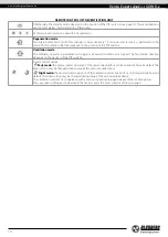
Страница 13: ...the ventilation unit in the air supply mode This mode may be activated only via the mobile application Filter 90 days after installation of the cartridge the filter replacement indicator starts glowing In this case clean or replace the filters see the Technical maintenance section After replacement of the filters reset the timer using the mobile application or by pressing and holding the button on...

Страница 14: ...or operates in permanent air supply or air extraction mode at set speed The fan rotation direction depends on the position of the DIP switch 3 Timer control buttons Party mode the timer activates operation of the unit at Speed III for a set time period 4 hours by default The timer setting may be changed during setup of the unit on mobile device Night mode the timer activates operation of the venti...

Страница 15: ... a Wi Fi access point FAN 16 characters of the ID number indicated on the control board of the ventilator Wi Fi access point password 11111111 1 2 4 5 6 8 7 3 Enter the Blauberg Vento V 2 app and create a new connection by following the steps below 1 Enter the app menu 2 Select Connection At home 3 If the mobile device is connected to the Wi Fi access point of the unit without a router select the ...

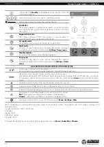
Страница 16: ...to the ventilator Home connection or connection via a cloud server through Internet respectively Speed III activation indicator It goes on after activation of any sensor Whenthismodeisactivated alltheothermodesaredeactivated Uponelapseoftheturn offdelaytimercountdown 30 minutes by default the ventilation unit reverts to the previous mode Press Power to deactivate this operation mode Humidity indic...

Страница 17: ...rs Humidity sensor activation of the humidity sensor When the indoor humidity exceeds the set point the unit switches to Speed III When the humidity level drops below the threshold value the Boost turn off delay timer is activated When the timer elapses the ventilator reverts to the previous speed setting 0 10 V sensor activation of the external analogue sensor 0 10 V When a 0 10 V control signal ...

Страница 18: ...he Slave units If so replace the filters on all the ventilators on the network Upon filter timer reset the filter replacement warning is disabled on all the connected ventilators The filter timer can also be reset by means of the button on the indoor unit see page 14 To restore the factory settings via the mobile app go to Menu Settings Factory settings Then press the Reset to factory settings but...

Страница 19: ...he Receive button to display the current Wi Fi settings Select one of the Wi Fi operation modes Access Point access point mode without a home router Select the desired security level for the Access point mode Open open Wi Fi network without a password WPA PSK password protected Encryption technology using the WPA protocol which does not guarantee complete security WPA2 PSK password protected The t...

Страница 20: ...d by the technical characteristics of the router If the Wi Fi router capacity is not enough to connect a required number of the units you may use an extra wireless access point to connect the other the unit Several Master units can optionally be connected to the network for arranging a zone control To connect a master and a slave ventilator set the DIP switches on the units accordingly see page 13...

Страница 21: ...n button on the ventilator casing for 5 seconds until the beep and blinking of all the LED lights The ventilator will continue in this mode for 3 minutes and then automatically revert to the previous settings To exit the Setup mode immediately press and hold the Ventilation button on the ventilator casing once again for 5 seconds until the beep and shutdown of all the LED lights In this mode the f...

Страница 22: ...spective button if necessary 5 Enter a ventilator name of choice the ventilator ID as stated on the control circuit board and the unit password 1111 by default 6 Confirm the updated details To log into the account via the mobile app go to Menu Connection Through cloud server Then enter the login and password and press the Log in button The ventilators can be controlled using the mobile app via a c...

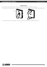
Страница 23: ...utomatically The unit functionality is not changed To open the air duct pull the front panel while holding the special recesses The fan starts operating according to the actual speed setting Air duct blocking Air duct opening The front panel incorporates an operating LED indicator During the dark time the indicator light intensity drops down ...

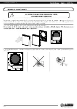
Страница 24: ...e of the indoor control unit to take off the front part Please make sure the thermal actuator rod is in lower position during re installation of the front panel If the thermal actuator rod is up please wait for about 2 minutes until it goes down Warning Prior to mounting the front panel make sure that the ther mal rod is in the low position and the indicator of the circuit board glows 2 Disconnect...

Страница 25: ...e filter rated service life is 3 years Some dust may accumulate on the heat exchanger block even in case of regular maintenance of the filters Clean the regenerator regularly to ensure its high heat recovery efficiency Vacuum clean the regenerator not less than once a year 4 Replacement of the remote control battery if necessary In case of a long operation of the remote control the battery must be...

Страница 26: ...r up after transportation at low temperatures allow the unit to warm up at operating temperature for at least 3 4 hours POSSIBLE REASONS AND TROUBLESHOOTING Problem Possible reasons Troubleshooting When switching on the ventilator the fan does not start No power supply Make sure the power supply line is connected correctly otherwise troubleshoot the connection error The motor is jammed the impelle...

Страница 27: ...l Contact the Seller for warranty service The manufacturer s warranty does not apply to the following cases User s failure to submit the unit with the entire delivery package as stated in the user s manual including submission with missing component parts previously dismounted by the user Mismatch of the unit model and the brand name with the information stated on the unit packaging and in the use...

Страница 28: ...www blaubergventilatoren de Vento Expert A50C3 1 S8 W V 2 28 ...

Страница 29: ...www blaubergventilatoren de Vento Expert A50C3 1 S8 W V 2 29 ...

Страница 30: ...www blaubergventilatoren de Vento Expert A50C3 1 S8 W V 2 30 ...

Страница 31: ...ed and accepted Customer s Signature The Vento Expert _________________ unit is installed pursuant to the requirements stated in the present user s manual Installation Stamp Company name Address Phone Number Installation Technician s Full Name Installation Date Signature The unit has been installed in accordance with the provisions of all the applicable local and national construction electrical a...

Страница 32: ...www blaubergventilatoren de B133 6EN 01 ...

Отзывы: