background image

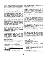
Valet Mode
When the Valet mode is activated, the vehicle will
not start using the remote, but keyless entry
functions will still operate.
To enter valet mode:

1. Turn ignition to the on position.
2. Within 5 seconds, press and hold

program switch for approximately 2 seconds.
• The LED will light solid 

To exit valet mode:

1. Turn ignition to the on position.
2. Within 5 seconds press and hold program

switch for approximately 2 seconds.

The LED will turn off

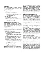
Adding or Deleting Remote Controls
When you enter the code learning mode, the
system will learn new remotes and automatically
delete all other remotes that were previously
operating the system.

NOTE: You must code all desired remotes at this
time. The remote start unit can learn a maximum
of three codes.
To enter Code Learning Mode:

1. Turn ignition key on, off, on, off, and leave on

within 5 seconds.
LED will flicker and parking lights will flash
once.

2. Press and hold program switch for 2 seconds.
3. LED will flicker and parking lights will flash.
4. Release the program switch.
5. Program all desired remotes by pressing

button #1 on each of the transmitters. The
parking lights will flash after the system has
learned each remote control.

6. Turn ignition key off. Remotes are now

programmed to the system.

Bypassing Factory Theft Deterrent Systems
Many newer vehicles are now factory-equipped

with anti-theft systems that use either a resistor
coded key or a passive transponder that disables
the fuel system unless a properly coded key is
inserted into the ignition cylinder. To integrate a
remote starter into these vehicles, you must
determine which type of factory anti-theft system is
equipped, then use the proper bypass module for
that system.

General Motors Anti-theft Systems:
Many late-model GM vehicles are equipped with
one of three basic anti-theft systems; Passkey,
Passlock, and Passkey 3.

Standard Passkey

systems are easily identified by the resistor chip
visible on the shaft of the key. Passlock systems do
not rely on a resistor equipped key. Instead they use
a resistance code generated when the key is turned
in the ignition cylinder. Both of these systems have
an anti-theft indicator in the  instrument cluster.
To properly interface into these systems and retain
full functionality of the factory anti-theft system, use
the APV-1 module.
The Passkey 3 system, which is found on GM
vehicles 1999 and newer, is a transponder based
system (described below). Use the APP-1  module
to integrate into Passkey 3 equipped vehicles. This
module allows full functionality of the factory anti-
theft system and requires the use of a spare key.

Passive Transponder  Systems:
Passive transponder systems have become the
most popular anti-theft system among vehicle
manufacturers (Ford, Honda, BMW, Toyota, Nissan
and others). This system requires use of a tiny
passive transmitter housed in the base of the key.
This device activates when placed close to the
vehicle’s ignition switch. The starter will usually
crank but the fuel system will be disabled, mot
allowing the vehicle to run, if the transponder is not
detected. To properly interface into transponder
systems, use the APP-1 module. This module allows
full functionality of the factory anti-theft system and

5

Содержание BW RAS 400

Страница 1: ... 2 heavy duty fuse holders Hood pinswitch Extended range receiver module Owner s manual S models are provided with single transmitter only Add on modules do not include transmitters OPTIONAL ACCESSORIES VAC 10 Vacuum Switch Kit APP 1 Universal OEM transponder bypass kit APV 1 GMVATS Passlock I II bypass kit PDLM 3 Power door lock relay module Before you begin the installation Verify that the vehic...

Страница 2: ...onnect to the main ignition wire that switches 12 V and does not drop out during cranking ORANGE WIRE Main accessory output This provides 12V output to heater and or air conditioning system Some cars may have more than one accessory wire In these vehicles add a relay s to power the extra accessory wire s PURPLE WIRE Starter output connect to the vehicle s starter wire Main Harness WHITE WIRE Parki...

Страница 3: ...EDWIRE constant 12V low current output for relay modules or inverters 100mA relay trigger only Do NOT use as a power source for door lock relays GREENWIRE negative lock output 3 Pin Red Connector Plug in connector port for optional features harness GREEN BLACK WIRE 3rd channel output Connect to a relay for optional trunk release etc RED WIRE Factory Disarm output Connect to the wire that requires ...

Страница 4: ...activates Off Disabled Default Reset To reset all programmable features to their factory default settings 1 Turn ignition to the on position 2 Wait 2 seconds 3 Within 10 seconds press program switch 5 times The LED and parking lights flash to indicate the system is now in program mode 4 Press transmitter buttons 1 2 The parking lights will flash 3 times and all programmable features will be reset ...

Страница 5: ...the ignition cylinder To integrate a remote starter into these vehicles you must determine which type of factory anti theft system is equipped then use the proper bypass module for that system General Motors Anti theft Systems Many late model GM vehicles are equipped with one of three basic anti theft systems Passkey Passlock and Passkey 3 Standard Passkey systems are easily identified by the resi...

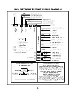
Страница 6: ...N the ignition OR remote start the vehicle WIRING HARNESS RED YELLOW IGNITION 1 OUTPUT BROWN IGNITION 2 OUTPUT RED CONNECT DIRECTLY TO THE BATTERY GREEN SPARK OR TACH SENSE VIOLET NOT USED BLACK GROUND INPUT ORANGE ALARM AUXILIARY INPUT WHITE PARKING LIGHT OUTPUT RED 12V INPUT SWITCH HOOD SWITCH INPUT BLUE BROWN NOT USED GRAY REMOTE START OUTPUT VIOLET STARTER OUTPUT ORANGE ACCESSORY OUTPUT YELLOW...

Страница 7: ...s not working Use either the spark sense or tach sense Vehicle has a factory theft deterrent system that prevents starting w o key in ignition Suggested Correction Main Inputs heavy gauge red wires and small red wire on main harness must be connected to 12V Turn ignition key to on position press and hold service switch for 5 seconds The LED will turn off Check Brake Switch Input Yellow Wire or Hoo...

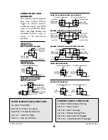
Страница 8: ...IN HARNESS CUT X TO BATTERY TO STARTER MOTOR IGNITION SWITCH PURPLE WIRE HEAVY GAUGE 87 87a 86 30 85 87 87a 86 30 85 87 87a 86 30 85 87 87a 86 30 85 87 87a 86 30 85 87 87a 86 30 85 87 87a 86 30 85 87 87a 86 30 85 87 87a 86 30 85 87 87a 86 30 85 87 87a 86 30 85 87 87a 86 30 85 87 87a 86 30 85 HORN HONK DIAGRAM DOME LIGHT DIAGRAM GROUND WHITEWIRE FROMALARM 12V IGNITION 2001 DLC INC 64 400 8 01 Rev 2...

Отзывы: