724-746-5500 | blackbox.com
724-746-5500 | blackbox.com
Page 21
Chapter 5: GUI Operation
5.3 GUI Port Description
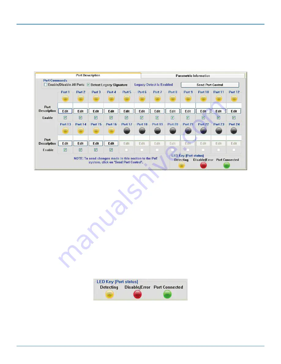
The Port Description panel shows 16 ports. On the 8- or 16-Port PoE Gigabit Injector models, the port numbers higher than the
system port count will be shaded gray and disabled. Each section specifies the individual port descriptions for the system.
Figure 5-5. Port Description.
To enable changes to the port configuration in this section, click the “Send Port Control” button. It will send the port information
to the unit for 16 ports. Allow the GUI 10 seconds to refresh.
Port Description: Click “Edit” to edit/change the description of the port. Click “OK” to set the description on the GUI screen. If
you click “Cancel,” the previous description will be set for that particular port. Click “Send Port Control” to send the descriptions
to the system. To make this permanent, you must click “Save Parameters to Flash.”
Enable: This check box can administratively enable or disable the selected port. If you select the “Enable/Disable All Ports” check-
box, all ports will be enabled. Initially, the checkbox is not checked, by default all ports are enabled. Click “Send Port Control” to
send the command to the system. To make this permanent, you must click “Save Parameters to Flash.”
If “Detect Legacy Signature” checkbox is selected, all ports are enabled and the firmware will try to detect legacy devices. By
default, legacy detection is disabled. The message in blue states that the “Legacy Detect is Enabled” (Figure 5-5). Click “Send
Port Control” to send the command to the system. To make this permanent, you must click “Save Parameters to Flash.”
The different colored LEDs show the status of the individual ports. A Yellow LED shows the port is detecting or ready to be con-
nected. A Red LED shows the port as Disable/Error. A Green LED shows that the port is connected to a compliant load.
Figure 5-6. LED key (port status).


