Black Box BOXILLA BXAMGR Скачать руководство пользователя страница 12

12

1.877.877.2269

BLACKBOX.COM

NEED HELP?

LEAVE THE TECH TO US

LIVE 24/7

TECHNICAL

SUPPORT

1.877.877.2269

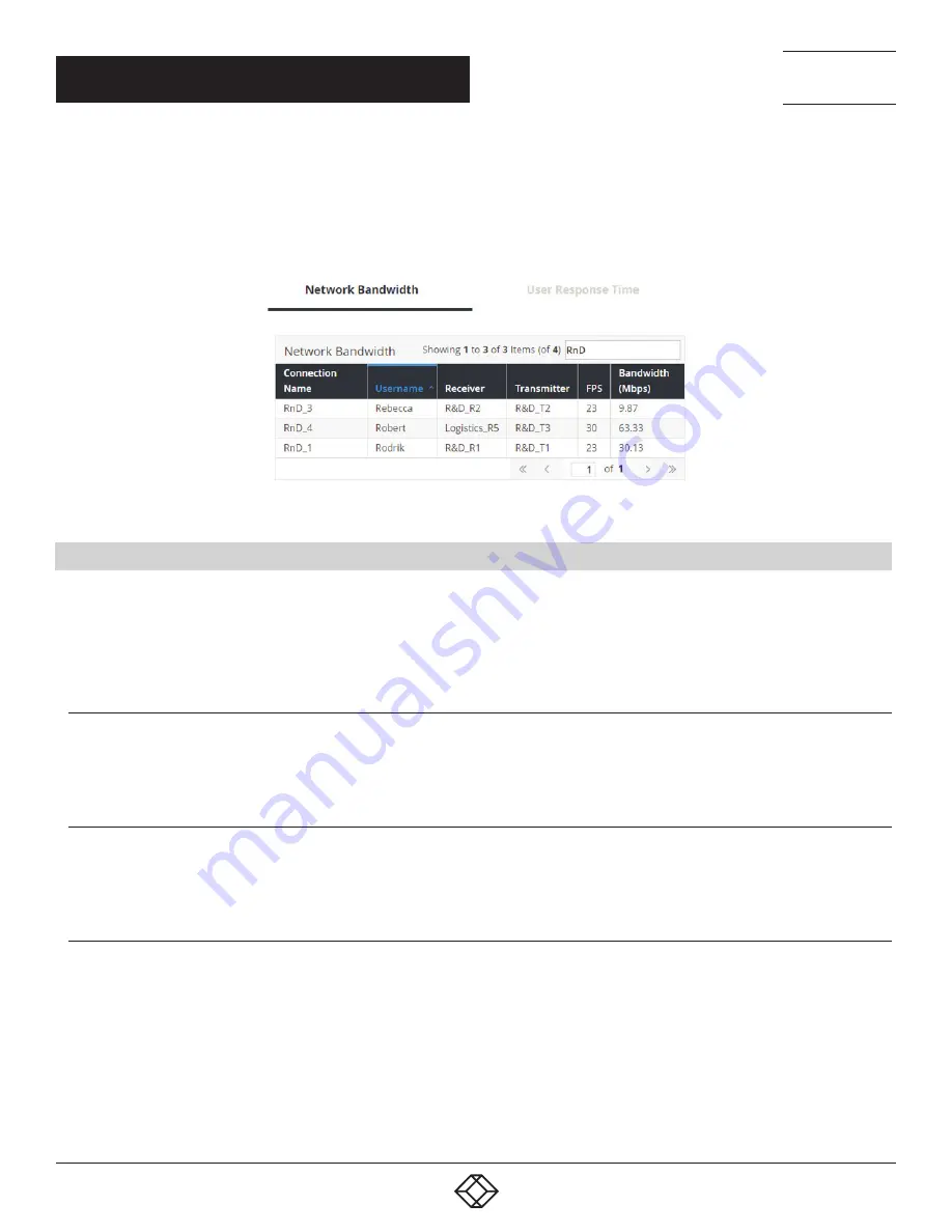
A common feature of tables in Boxilla is that they can be sorted by each column (alphabetically either ascending or descending). Click 
on the column’s label (e.g. Connection Name) and the table will be sorted by that column in ascending order. Click on the same column 
label again and the order will be reversed. Also, a filter can be applied to the values in the column to pick out a subset of rows in the table. 
For example, typing in RnD into the filter box in the Network Bandwidth table in Active Connection section of the Dashboard in Figure 3 
would result in three instead of four rows being displayed as shown in Figure 4.

FIGURE 4. FILTERING TABLE

2.4 MODES OF OPERATION  

 
The InvisaPC system has various modes of operation, such as Auto-Login, Auto-Connect, Private Connection and Shared 
Connection Modes. The InvisaPC devices can obtain their IP address data from a DHCP server in any of these modes or use static 
addresses. For stable operation with Boxilla, we strongly recommend that Static IP addresses are assigned to InvisaPC devices or 
that you use DHCP addresses with “infinite time-outs.”

2.4.1 AUTO LOGIN 


In Auto-Login Mode, turning on the InvisaPC Receiver automatically causes a login as a pre-defined user. The user is presented  
with the permitted connections that have been predefined.

2.4.2 AUTO CONNECT 


In Auto-Connect Mode, when a user logs-in to the InvisaPC Receiver, it causes an automatic connection to their pre-allocated 
workstation or virtual desktop. Auto-Login and Auto-Connect are defined independently of each other.

2.4.3 PRIVATE CONNECTION  

 
In Private Connection Mode, when a user makes a connection to a target workstation/virtual desktop, this connection is only accessible 
by this user. All other users will receive a “busy” message if they attempt to connect to the same workstation/virtual machine. This is the 
default mode for connections.

CHAPTER 2: PRODUCT OVERVIEW

Содержание BOXILLA BXAMGR

Страница 1: ...BXAMGR USER MANUAL 24 7 TECHNICAL SUPPORT AT 1 877 877 2269 OR VISIT BLACKBOX COM BOXILLA KVM AV IT MANAGER BOXILLA AV l IT MANAGER...

Страница 2: ...owser Configuration of IP Address 18 4 6 Mounting Boxilla in a Rack 19 4 6 1 Rackmount Safety Considerations 19 5 BOXILLA CONFIGURATION 21 5 1 Supported Browsers 21 5 2 Login 21 5 3 Important First Co...

Страница 3: ...la Unit Firmware 66 11 2 System Boxilla Licensing 67 11 3 System Certificates Upload 69 11 4 System Backup Restore 72 11 5 System System Info 72 11 6 System Thresholds 73 11 7 System Network 73 11 8 S...

Страница 4: ...portant operating and maintenance servicing instructions in the literature accompanying the appliance DANGEROUS VOLTAGE This symbol is intended to alert the user to the presence of uninsulated dangero...

Страница 5: ...RT 1 877 877 2269 SYMBOLS USED IN THIS MANUAL POWER OFF This symbol indicates the principal on off switch is in the off position PROTECTIVE GROUNDING TERMINAL This symbol indicates a terminal that mus...

Страница 6: ...C input 120 240 V 50 60 Hz Power Dissipation 75 W PSU rated for 250 W Dimensions System 1 73 H x 17 3 W x 10 6 D 4 4 x 44 x 26 8 cm Shipping box 7 2 H x 22 4 W x 15 4 D 18 5 x 57 x 39 cm Weight System...

Страница 7: ...sers with Receivers that communicate with target compute nodes whether physical PC or virtual desktop over a standard TCP IP network Physical PCs Workstations Servers have an InvisaPC Transmitter unit...

Страница 8: ...INCLUDING PHYSICAL AND VIRTUAL DESKTOPS 2 1 OVERVIEW OF BOXILLA CONCEPTS The InvisaPC family is composed of Receivers Transmitters and Managers Boxilla is the Enterprise class Manager for InvisaPC and...

Страница 9: ...ions defines how a Receiver can connect to a Transmitter or a Virtual Machine with properties such as private or share mode USB re direction enabled or disabled among others Alerts events detected by...

Страница 10: ...10 1 877 877 2269 BLACKBOX COM NEED HELP LEAVE THE TECH TO US LIVE 24 7 TECHNICAL SUPPORT 1 877 877 2269 FIGURE 2 BOXILLA DASHBOARD EXAMPLE CHAPTER 2 PRODUCT OVERVIEW...

Страница 11: ...h Receiver has a copy of the database This enables each Receiver to continue operation log users in make connections as required even if the Manager goes off line 2 3 BOXILLA SCREEN LAYOUT Boxilla is...

Страница 12: ...ction Modes The InvisaPC devices can obtain their IP address data from a DHCP server in any of these modes or use static addresses For stable operation with Boxilla we strongly recommend that Static I...

Страница 13: ...board and mouse of that computer Non keyboard and mice devices are not supported on shared connections These various modes can be mixed on a particular Receiver and connection For example Auto Login a...

Страница 14: ...isually lossless video over standard low bandwidth networks rather than a proprietary connection or dedicated gigabit networks of many systems 3 1 VIDEO AUDIO AND USB SWITCHING Numerous applications r...

Страница 15: ...he Boxilla package have been verified the first task is to configure the IP address of the unit This can be set in two ways 1 using the serial port and 2 using the network port via browser Serial Netw...

Страница 16: ...z CONNECT THE POWER 1 Locate the AC line cord 2 Attach the AC line cord to the power supply connector on the rear of the unit 3 Power up the unit by turning on the power switch on the back of the unit...

Страница 17: ...oxilla on leaving the factory is 192 168 1 24 and needs to be configured to an appropriate address for where it will be deployed To access the serial menu connect to the DB9 connector on the front of...

Страница 18: ...ILLA LOGIN SCREEN NOTE Only the Network port pointed to in Figure 6 on the right hand side one when you look at the Boxilla unit from the front is currently operational The other port is reserved for...

Страница 19: ...losed rack assembly the operating temperature of the rack environment may be greater than room ambient Use care not to exceed the rated maximum ambient temperature of the Boxilla unit Reduced Air Flow...

Страница 20: ...20 1 877 877 2269 BLACKBOX COM NEED HELP LEAVE THE TECH TO US LIVE 24 7 TECHNICAL SUPPORT 1 877 877 2269 FIGURE 12 ESD CONNECTION CHAPTER 4 INITIAL INSTALLATION...

Страница 21: ...Firefox Safari NOTE For the best experience always use the latest versions of supported browsers 5 2 LOGIN Ensure the Boxilla unit is powered up Wait two minutes after applying power before attempting...

Страница 22: ...22 1 877 877 2269 BLACKBOX COM NEED HELP LEAVE THE TECH TO US LIVE 24 7 TECHNICAL SUPPORT 1 877 877 2269 FIGURE 14 BOXILLA INITIAL SCREEN ON LOGIN CHAPTER 5 BOXILLA CONFIGURATION...

Страница 23: ...rst actions Click on System button on the main menu and then select the Users tab as shown in Figure 15 Click the icon on the Admin row and click on the edit option FIGURE 15 CHANGING ADMIN USER PASSW...

Страница 24: ...ver 2 Change the default password for the default user Admin for security NOTE Make sure that your computer can view the new IP address otherwise the Boxilla server will appear to be offline Depending...

Страница 25: ...ross multiple subnets If the InvisaPC discovery protocol is not enabled i e routers do not have multicast routing enabled the administrator will have to manually add in devices not on its subnet i e a...

Страница 26: ...Manager and that of the device This may occur where the device was removed from the Manager s database when the device was off line or if the Manager was restored to factory default settings A device...

Страница 27: ...en specified an unmanaged device can now be set to be part of this Boxilla s managed domain This is done by clicking on the Manage option shown in Figure 18 This causes the device s state to change fr...

Страница 28: ...P address of the device to be added and click on Get Information This causes Boxilla to retrieve the device s information if reachable If Boxilla has no valid path on the network to the device or IP a...

Страница 29: ...s the power button to be pressed Auto Login whether an InvisaPC Receiver will automatically login as a specific user on power up OSD Resolution resolution that the OSD is displayed at when on screen T...

Страница 30: ...at are part of the managed domain Boxilla constantly polls devices to determine their state and operational statistics The state of a device in the table can be Online means the device is contactable...

Страница 31: ...iguration Operational Status Firmware Version and Serial Number Ping tests the reachability of the device on the network Force Logout logs out the current user attached to this unit if any UnManage re...

Страница 32: ...ed To select a specific firmware release click the Activate button for the specific version of firmware from the Release options icon For InvisaPC this needs to be done for both Receivers DTX R and Tr...

Страница 33: ...UPGRADE SELECTION Once the administrator has selected devices to be upgraded typically all devices that mis match the active firmware version the administrator clicks the Upgrade button on the page to...

Страница 34: ...hanges take effect This is done on the Devices Settings page as shown in Figure 26 The admin changes the settings and then clicks Apply Changes only take effect when Apply is clicked The properties th...

Страница 35: ...l Hot Key is enabled It also means the Hotkey P switch to previous target is no longer is enabled The Enable Function key is set by default 7 3 2 RDP CONNECTION RESOLUTION This defines the resolution...

Страница 36: ...al VM from the pool and this is the IP address used for a connection from the InvisaPC Receiver NOTE We currently do not cater for hostnames so use the IP of the connection broker server When Connecti...

Страница 37: ...is is the default setting 2 If the Broker Connection Type is set to Web Access Server the Receiver will attempt to launch a connection to an RD Web Access server This will allow the user to be Authent...

Страница 38: ...displayed showing what user is logged in to what device when they logged in and how long they were logged in FIGURE 28 CONNECTIONS MANAGE SCREEN The table shows the connection name whether the connec...

Страница 39: ...pecific connection row The parameters for a connection are defined in more detail in section 8 1 1 8 1 1 CONNECTIONS ADD CONNECTION To allow an InvisaPC Receiver to connect to a target InvisaPC Transm...

Страница 40: ...r the new connection The name can be between 1 and 32 characters The name can be composed of any Alphanumeric characters and special characters except for IP Address Hostname the IP address of the Inv...

Страница 41: ...his setting has no effect on a single video head InvisaPC USB Redirection When set this enables non keyboard and non mice devices to be redirected for this connection Audio When set this enables audio...

Страница 42: ...ion template click Connection Template and this launches a screen that shows a list of connection templates Select the template s to be deleted and click on delete Boxilla will only display the list o...

Страница 43: ...add a connection group FIGURE 34 ADD CONNECTION GROUP SCREEN To dissolve a connection group Map Connections from Connection Group to Individual Connections FIGURE 35 DISSOLVE CONNECTION GROUP SCREEN...

Страница 44: ...Group Delete the Connection Group and everywhere it is used FIGURE 37 DELETE THE CONNECTION GROUP Confirm with OK and a confirmation message about deletion is displayed FIGURE 38 CONFIRM DELETION The...

Страница 45: ...the connection the Receiver in the connection the user who is logged into the Receiver the type of connection e g private or shared the Transmitter in the connection and then statistics on the connec...

Страница 46: ...46 1 877 877 2269 BLACKBOX COM NEED HELP LEAVE THE TECH TO US LIVE 24 7 TECHNICAL SUPPORT 1 877 877 2269 FIGURE 40 ACTIVE CONNECTIONS CHAPTER 8 CONNECTIONS...

Страница 47: ...f this class can modify resolution for connections to virtual desktops and change his her local password 3 Standard Users Users of this class can only select from a list of pre defined connections to...

Страница 48: ...password can be any valid password for a Microsoft O S This means the password cannot contain User Privilege This field defines the type of user the new user will be Administrator General User or Powe...

Страница 49: ...ected List and then click the button This causes the selected connections to be added to a user s selected connection window as shown in Figure 43 Click Save to complete the selection It is a similar...

Страница 50: ...1 877 877 2269 CHAPTER 9 USERS 9 3 USER ACTIVE The User Active page shows a list of all the users logged in to an InvisaPC Receiver The page provides information on what Receiver the user is logged in...

Страница 51: ...ty onto the network where Boxilla will recognize it and remotely initiate the desired connections on the attached InvisaPC Receivers The above can be achieved by following these steps 1 Create and man...

Страница 52: ...1 877 877 2269 CHAPTER 10 DKM INTEGRATION FIGURE 46 CREATE A VIRTUAL CPU OPTION You will then have the option to name your Virtual CPU IMPORTANT This name must be the same as the InvisaPC Connection...

Страница 53: ...which appears under the Assignment tab on the main menu on the left side of the application window Here you can assign your new Virtual CPU to the real CPU that s physically connected into your Invis...

Страница 54: ...E THE TECH TO US LIVE 24 7 TECHNICAL SUPPORT 1 877 877 2269 CHAPTER 10 DKM INTEGRATION Next click Save Online Changes This pushes the changes down to the DKM switch so even if it reboots it will hold...

Страница 55: ...877 877 2269 CHAPTER 10 DKM INTEGRATION HOW TO ENABLE LAN ECHO Next you must Enable LAN Echo This will enable the switch to echo the results of the connection initiations to the network where Boxilla...

Страница 56: ...STEPS TO ADD SWITCHES Under Boxilla to add the DKM switch navigate to DKM Switches and click the Add Switch blue button on the top right of the screen FIGURE 51 ADD SWITCH SCREEN The Add new switch bo...

Страница 57: ...T 1 877 877 2269 CHAPTER 10 DKM INTEGRATION Once the switch is added successfully it gets listed with an online status FIGURE 53 ONLINE STATUS OF SWITCH If you wish to revert select Delete from the dr...

Страница 58: ...A SWITCH Once the switch is added successfully all DKM CONs and DKM CPUs physical connected will be listed on Boxilla Also any Virtual CPUs configured on the DKM switch will be listed Boxilla will aut...

Страница 59: ...INTEGRATION Find the Virtual CPU in the Ports list on the DKM Switches page Click the options button on the right hand side to Attach to InvisaPC Connection FIGURE 57 ATTACH TO INVISAPC CONNECTION If...

Страница 60: ...vailable sources to activate which will create connections with the selected sources FIGURE 59 ADD CUSTOM SOURCE SCREEN Once these connections are listed each connection needs at least one destination...

Страница 61: ...VE THE TECH TO US LIVE 24 7 TECHNICAL SUPPORT 1 877 877 2269 CHAPTER 10 DKM INTEGRATION FIGURE 60 MANAGE PRESETS BUTTON FIGURE 61 ADD DESTINATION POPUP BOX Search of available destinations can be comp...

Страница 62: ...7 TECHNICAL SUPPORT 1 877 877 2269 CHAPTER 10 DKM INTEGRATION FIGURE 62 ADD DESTINATION POPUP BOX ACTIVATE SELECTED BUTTON Active connections are listed under the Connections link Each connection has...

Страница 63: ...SUPPORT 1 877 877 2269 CHAPTER 10 DKM INTEGRATION 10 5 PRESETS Under Viewer click Manage Presets then click Create Custom and select one or more available sources FIGURE 64 CREATE CUSTOM PRESETS Next...

Страница 64: ...e is applied to all the CONS and CPUS Any CONs and CPUs not selected in this preset type will become inactive when this preset is launched Click Complete to save the preset FIGURE 66 PRESETS SCREEN Th...

Страница 65: ...tions started via Presets will be displayed in the work area with the following options 1 Detach Source Break the connection by detaching the source 2 Detach Destination Break the connection by detach...

Страница 66: ...EN UPGRADE 11 1 SYSTEM UPGRADING BOXILLA UNIT FIRMWARE To upgrade the firmware on the Boxilla unit choose the file to be used to upgrade and click on submit as shown in Figure 69 and follow the instru...

Страница 67: ...of BXAMGR LIC25 25 more devices users connections BXAMGR LIC100 100 more devices users connections BXAMGR LIC ULT unlimited more devices users connections Licenses can be added under System Page Lice...

Страница 68: ...7 2269 BLACKBOX COM NEED HELP LEAVE THE TECH TO US LIVE 24 7 TECHNICAL SUPPORT 1 877 877 2269 FIGURE 71 ADD LICENSE SCREEN Once you receive the license file upload the new license FIGURE 72 UPLOAD LIC...

Страница 69: ...mation The new system allows the users to upload these files into Boxilla so they can upload the other key into their browser This will then act as an authenticated certificate and the user will no lo...

Страница 70: ...BOX COM NEED HELP LEAVE THE TECH TO US LIVE 24 7 TECHNICAL SUPPORT 1 877 877 2269 CHAPTER 11 SYSTEM FIGURE 74 UPLOAD CERTIFICATE BUTTON FIGURE 75 SELECT THE CERTIFICATE FILE A green alert on the page...

Страница 71: ...24 7 TECHNICAL SUPPORT 1 877 877 2269 FIGURE 76 GREEN ALERT To delete any existing certificates click on the delete cert button under certificates tab FIGURE 77 DELETE BUTTON A popup message will be d...

Страница 72: ...nto the Backup Table Once the upload has been completed the administrator clicks on Import on the icon options on the row on the Backup table to be used to restore the Boxilla unit settings Clicking o...

Страница 73: ...l or at info level Measurements above the Warning Threshold and below Critical Threshold are classified as at Warning level Measurements at or above the Critical Threshold are classified as Critical l...

Страница 74: ...The Clock tab enables the Administrator to see the current system time and to change it as shown in Figure 81 FIGURE 81 CLOCK OR TIME SETTINGS 11 9 SYSTEM USERS The Users tab shows a table of users f...

Страница 75: ...75 CHAPTER 1 HEADLINE 1 877 877 2269 BLACKBOX COM NEED HELP LEAVE THE TECH TO US LIVE 24 7 TECHNICAL SUPPORT 1 877 877 2269 CHAPTER 11 SYSTEM FIGURE 83 NEW SYSTEM USER...

Страница 76: ...fied as a Warning Alert Events that indicate a potential serious negative impact on the system is classified as a Critical event Events that are classified as Critical are Failure to update the IP Add...

Страница 77: ...just Critical Warning or Info by selecting the appropriate tab on the Alerts History screen as shown in Figure 84 FIGURE 84 ALERTS HISTORY 12 2 ALERTS ACTIVE Active Alerts are alerts that are current...

Страница 78: ...are counted on each Receiver when a user fails a login attempt Unauthorized Connections are counted on Receivers and Transmitters when they detected something has attempted to connect to them in an un...

Страница 79: ...Receiver on the active connection Transmitter the name of the Transmitter on the active connection FPS the current frames per second being encoded transferred on the connection The contents of the la...

Страница 80: ...n the filter box contents The table portion has the following columns Receiver the receiver name that has been logged into Username the user name that has logged into the Receiver User Type the type o...

Страница 81: ...an InvisaPC Receiver or Transmitter All the parameters in section 13 1 need to be locally set on each individual Receiver and those in section 13 2 need to be set locally on each Transmitter as requi...

Страница 82: ...A SWAPPING OUT A BOXILLA SERVER This section defines what an Administrator should do to ensure the Boxilla unit can be replaced and the system restored with its previous settings A key maintenance ta...

Страница 83: ...han where the Manager is located to be discovered InvisaPC devices respond to the discovery multicast by sending a UDP unicast back to the Manager IP address on the same port Port 39150 Once an Invisa...

Страница 84: ...compliance could void the user s authority to operate the equipment This digital apparatus does not exceed the Class A limits for radio noise emission from digital apparatus set out in the Radio Inter...

Страница 85: ...__________ _ _________________________________________________________________________________________________ _________________________________________________________________________________________...

Страница 86: ...__________ _ _________________________________________________________________________________________________ _________________________________________________________________________________________...

Страница 87: ...__________ _ _________________________________________________________________________________________________ _________________________________________________________________________________________...

Страница 88: ...NEED HELP LEAVE THE TECH TO US LIVE 24 7 TECHNICAL SUPPORT 1 877 877 2269 COPYRIGHT 2017 BLACK BOX CORPORATION ALL RIGHTS RESERVED...

Отзывы: