ENGLISH
ENGLISH
15
16
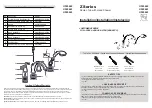
FAUCET FUNCTIONS
14
13
12
11
16 FLUSHING & AERATOR CLEANING
After installation is complete, remove Aerator Housing (
16A
). Turn Valve (
16B
) on
and allow both hot and cold water to run for at least one minute each. While water is
running, check for leaks. To clean the aerator, disassemble Aerator Housing (
16A
) by
separating the Aerator Shell (
16C
), Basket (
16D
), and Washer (
16E
). Once parts have
been cleaned, reassemble by reversing steps.
15 SIDE SPRAY OPERATION
The Side Spray (
15A
) can be pulled forward to spray water in any direction. To activate the
Side Spray, press the Toggle Button (
15B
) located on the back of the Side Spray (
15A
).
14 FAUCET FUNCTION
By lifting the Lever Handle (
14A
) up, the valve will be activated allowing water to flow.
The water flow will increase by continuing to lift up the Lever Handle (
14A
). By rotating
the Lever Handle counter-clockwise, the water temperature will decrease to cold flow
only. By rotating the Lever Handle clockwise, the water temperature will increased to
hot flow only.
The Spout (
14B
) can be rotated around the Faucet Body in any direction.
13 UNIT START UP
Turn on hot and cold water supplies, and check for leaks above and below the sink.
Note:
After installation is complete, flush faucet (
see step 16
).
11 SIDE SPRAY INSTALLATION
Insert Side Spray Hose (
11A
) through Hose Guide (
11B
).
From underneath sink, push Quick Connect Housing (
11C
), located on the end of the Spray
Hose (
11A
), firmly upward onto the receiving Tube (
11D
), until unable to push any further.
Pull down on the quick connect housing (
11C
). If the housing and the Inner Collet (
11E
)
separate slightly, but do not pull off the receiving Tube (
11D
), quick connect is secure.
12 WATER SUPPLY LINES
Gently separate hot and cold supply tubes (
12A
), approximately three inches apart.
Connect water Supply Lines (
12C
) to Faucet Inlets (
12B
). Hot water supply line goes
to hot inlet fitting indicated by red tag (
12D
). (
Supply lines not included
). Follow
manufacturer’s instructions when installing supply lines.
Do not twist
supply tubes
(
12A
)!
4
15B
15A
16A
16C
16D
16E
16B
14A
14B
HOT
COLD
ON
14A
12A
12A
12C
12C
12D
12B
12B
HOT
COLD
11A
11C
11D
11E
11C
11D
11C
11B
11A
11B