5
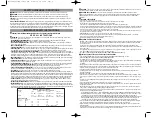
Controls and Indicators
CHARGING/RECHARGING
This product has a sealed lead acid battery. For maximum battery life, we recommend the Jump-Starter be kept fully charged at
all times. Recharge before first use, immediately after each use, and once a month if not used. Failure to do this may reduce the
battery life dramatically. To check the battery charge status at any time, press the Battery Charge Level Pushbutton.
Note:
This unit is delivered in a partially charged state – you must fully charge it before using it for the first time. Initial AC
charge should be for 24 hours.
Charging/Recharging Using the 120 Volt AC Charger and
a Standard Household Extension Cord (not included)
1. Lift the AC adapter cover located on the back of the unit and connect an extension cord to the unit. Plug the other end of the
cord into a standard 120 volt AC wall outlet.
2. Charge until three Red and one Green LED Battery Status Indicators light.
3. Once fully charged, disconnect the extension cord.
Note:
The unit cannot be overcharged using the AC method.
JUMP-STARTER
This Jump-Starter is equipped with an ON/OFF Power Switch. Once the connections are properly made, turn the switch ON to
jump-start the vehicle.
1. Turn OFF vehicle ignition and all accessories (radio, A/C, lights, connected cell phone chargers, etc.). Place vehicle in “park”
and set the emergency brake.
2. Make sure the Jump-Starter Power Switch is turned to OFF.
3. Remove jumper clamps from clamp tabs. Connect the red clamp first, then the black clamp.
4.Procedure for jump-starting a NEGATIVE GROUNDED SYSTEM (negative battery terminal is connected to chassis) (MOST
COMMON)
4a. Connect positive (+) red clamp to vehicle battery’s positive terminal.
4b. Connect negative (–) black clamp to chassis or a solid, non-moving, metal vehicle component or body part. Never clamp
directly to negative battery terminal or moving part.
5.Procedure for jump-starting POSITIVE GROUND SYSTEMS
Note:
In the rare event that the vehicle to be started has a Positive Grounded System (positive battery terminal is
connected to chassis), replace steps 4a and 4b above with steps 5a and 5b, then proceed to step 6.
5a. Connect negative (–) black clamp to vehicle battery’s negative terminal.
5b. Connect positive (+) red clamp to vehicle chassis or a solid, non-moving, metal vehicle component or body part. Never
clamp directly to Positive battery terminal or moving part.
1.REVERSE POLARITY INDICATOR
2.ALTERNATOR CHECK INDICATOR
3.JUMP-STARTER POWER ON INDICATOR
4.JUMP-STARTER POWER SWITCH
5.BATTERY CHARGE LEVEL PUSHBUTTON
6.USB POWER ON INDICATOR
7.USB POWER PORT
8.
USB ON/OFF SWITCH
9.LED BATTERY STATUS INDICATORS
10.BUILT-IN 120 VOLT AC CHARGER (UNDER
PROTECTIVE COVER)
11.POSITIVE (+) RED CLAMP
12.BUILT-IN LED EMERGENCY AREA LIGHT
13.AREA LIGHT POWER SWITCH
14.NEGATIVE (–) BLACK CLAMP
Front View
Back View
3
2
5
4
7
6
8
9
1
10
11
12
13
14
4
• Place this unit as far away from the battery as cables permit.
• Never allow battery acid to come in contact with this unit.
• Do not operate this unit in a closed area or restrict ventilation in any way.
•
FIRST AID
– SKIN: If battery acid comes in contact with skin, rinse immediately with water, then wash thoroughly with soap
and water. If redness, pain, or irritation occurs, seek immediate medical attention.
EYES: If battery acid comes in contact with eyes, flush eyes immediately, for a minimum of 15 minutes and seek immediate
medical attention.
•
IMPORTANT:
This unit is delivered in a partially charged state. Fully charge unit with a household extension cord (not supplied)
for a full 24 hours before using for the first time. You cannot overcharge the unit using the AC charging method.
• All On/Off switches should be in the OFF position when the unit is charging or not in use. Make sure all switches are in the OFF
position before connection to a power source or load.
• This system is designed to be used only on vehicles with a 12 volt DC battery system. Do not connect to a 6 volt or 24 volt
battery system.
• This system is not designed to be used as a replacement for a vehicular battery. Do not attempt to operate a vehicle that does
not have a battery installed.
• Excessive engine cranking can damage a vehicle’s starter motor. If the engine fails to start after the recommended number of
attempts, discontinue jump-start procedures and look for other problems that may need to be corrected.
• Do not use this jump-starter on a watercraft. It is not qualified for marine applications.
• Although this unit contains a non-spillable battery, it is recommended that unit be kept upright during storage, use and
recharging. To avoid possible damage that may shorten the unit’s working life, protect it from direct sunlight, direct heat
and/or moisture.
• Read And Understand This Instruction Manual Before Using This Unit.
SAVE THESE INSTRUCTIONS
WARNING: TO REDUCE THE RISK OF INJURY:
Follow these instructions and those published by the battery manufacturer and manufacturer of any equipment you intend to
use with this unit. Review cautionary markings on these products and on engine.
INTRODUCTION
Thank you for choosing the
500 Amp Slim Jump-Starter.
This compact jump-starter is unique in the amount of energy it can
supply for its size. The internal battery is a high density sealed, lead-acid battery that stores and delivers energy comparable to
full sized ordinary jump-starters. Please read this guide carefully before use to ensure optimum performance and avoid damage
to the unit or items that you are using it with.
The
500 Amp Slim Jump-Starter
is a compact, durable, portable jump-start system for vehicles that have a standard 12 volt
battery system. This self-contained, rechargeable system will start most vehicles without the need for a host vehicle or 12 volt
DC power supply. It can also be used as a portable source of 12 volt DC electric power in remote locations and/or emergency
situations. It is ideal for use with 12 volt DC cordless, portable, rechargeable products and DC/AC power inverters.
FEATURES
• Keyless ON/OFF Power Switch
• Cordless/rechargeable
• Built-in non-spillable, maintenance-free, heavy duty, sealed, lead-acid battery
• Requires no maintenance (other than recharging) for optimum operation
• Heavy duty cables and clamps
• 5 Volt DC USB Charging Port
• Built-in LED Area Light
• Alternator voltage check
• Reverse polarity connection warning indicator
• Exclusive cable storage channels keep jumper cables out of the way until needed
• Built-in 120 Volt AC Charger (uses a standard extension cord, not included)
• Easy-to-read LED battery charge status indicators
This device complies with part 15 of the FCC rules. Operation is subject to the following two conditions: (1) This device
may not cause harmful interference, and (2) This device must accept any interference received, including interference that
may cause undesired operation.
This equipment has been tested and found to comply with the limits for a Class B digital device, pursuant to part 15 of the
FCC Rules, These limits are designed to provide reasonable protection against harmful interference to radio
communications. However, there is not guarantee that interference to radio or television reception, with can be determined
by turning the equipment off and on, user is encouraged to try to connect the interference by one or more of the following
measures:
• Reorient or relocate the receiving antenna.
• Increase the separation between equipment and receiver.
• Connect equipment into an outlet on a circuit different from that to which the receiver is connected.
• Consult the dealer or an experienced radio/TV technician for help.
JU500B ManualEN 040308.qxp 4/3/2008 12:04 PM Page 4


