4
ENGLISH
(Original instructions)
5
ENGLISH
(Original instructions)
u
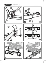
Insert the support brackets (1) into the square holes at
both ends of the stand, Figure C.
u
Place and tighten the adjustment screws (2) at both ends
of the stand, Figure C.
Attaching the mitre saw with supporting arms to
stand (Fig. D, E, F & G)
Prepare supporting arms (Fig. D)
u
Insert two M8 x 60 Bolts (9) into each mounting brackets.
Warning
! Turn off tool switch and disconnect power before
mounting to the stand. Unintended startup during assembly
can cause injury.
To ensure balance and stability when using the saw, all four
corners of the saw must be bolted to the mounting arms
before use. Make sure bolts do not extend above the table of
the mitre saw.
Attaching mitre saw to supporting arms (Fig. D, E)
The saw base has four holes that line up with the slots in the
mounting brackets. See Figure E.
Warning! Ensure that the handles (5a) of the mounting
brackets (5) are positioned to the rear of the mitre saw.
u
Place the mounting brackets downward.
u
Lift one side of the saw and place a mounting bracket
underneath, aligning the socket head cylinder cap screws
with mitre saw mounting holes, as shown in figure E.
u
Seat the mitre saw onto the mounting bracket, feeding the
socket head cylinder cap screws through each mounting
hole.
u
Use a plain washer and nut (11) to hold in position.
u
Repeat the above 4 steps to install second bracket to the
other side of the saw.
u
Make sure the brackets are parallel to each other. Use the
provided socket (10) to loosely fasten each nut.
Alternatively you can use an adjustable wrench..
Attaching the mitre saw and bracket assembly to
stand (Fig. F & G)
u
Lift the saw and bracket assembly, allowing the assembly
to tilt slightly toward your body.
u
When the the bracket assembly is tilted toward you, hook
its front edge onto the front rail of the stand, see Figure F.
Warning
! To avoid serious injury, before seating the rear
end of the bracket, make sure the curved front edge of the
mounting bracket are securely seated over the front rail .
Failure to do so could cause you to lose control of the saw
mounting assembly.
u
Lower the bracket assembly, allowing its rear edge to fully
seat over the rear rail, Figure G.
Note:
Use one hand to hold the mounting bracket assembly
until both levers are securely locked.
u
Check position and adjust if necessary, to make sure the
weight of the saw is evenly balanced over the rails as
shown in Figure G.
u
Ensure the saw is fully seated and locked in position, then
fully tighten the four nuts to hold the saw to the mounting
bracket.
Removing saw from stand
u
Loosen the locking arms to unlock the saw and mounting
bracket assembly.
u
Pull the locking handles in (5a).
u
Slightly tilt the assembly toward you, lift the front part of
the assembly to disengage from the front rail of the stand,
see Figure F.
The stand compatability test
With the saw mounted on the stand:
u
Check for fit and function. There shall be no interference
of mitre saw throughout the full range of mitre, bevel and
compound cut.
u
The Work Support can be adjusted to a height that is level
with the table top of the mitre saw.
Warning! Check that the stand is completely stable and does
not tip when pulling down the head of the mitre saw.
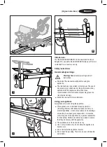
Using the side extensions (Fig. H & I)
u
Use the side extensions to support longer lengths of
wood.
Extending the rails
u
Loosen the locking screw (8).
u
Extend the side extensions to the desired position.
u
Tighten the side extension locking screw.
u
When the side extension has been extended to the
warning position, it should not be further extended.
Adjusting height of the support brackets
u
Loosen the support bracket adjustment screw at the end
of the side extension, as shown in Figure I. Lift the support
bracket to a height that is level with the table top of the
mitre saw.
u
Retighten knob and repeat on the opposite side.
Warning:
To reduce the risk of injury, make sure the support
brackets are adjusted so that the workpiece sits flat on the
mitre saw table. Workpieces that do not sit flat could cause the
blade to bind during cutting.
Carry Handle (Fig. J)
A handle (6) has been supplied to transport the mitre saw
stand to and from the work site.
WARNING:
To reduce the risk of personal injury, DO NOT
attempt to store the stand with the saw attached. Loss of
control may result.
Содержание BEZ100
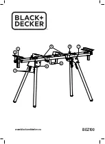
Страница 1: ...BEZ100 1 7 8 2 3 5 4 6 www blackanddecker eu ...
Страница 2: ...2 ENGLISH Original instructions 2 3 4 A 8 B 1 2 C 5 5 9 9 5a 5a D 10 11 E F ...
Страница 12: ...12 перевод с оригинала инструкции PУССКИЙ ...
Страница 13: ...13 перевод с оригинала инструкции PУССКИЙ ...
Страница 18: ...18 переклад з оригінальної інструкції УКРАЇНСЬКА ...
Страница 19: ...19 переклад з оригінальної інструкції УКРАЇНСЬКА ...
Страница 20: ...XXXXXXXX RUS UA 02 2020 ...

