4.
SERVICING
1.
The power supply to the unit must be disconnected prior to service.
2.
Most of the service to this unit can be performed from the front and/or the control panel side.
3.
For proper service, access to the control panel side of the unit is required.
4.
It is necessary to have access to the back of the oven when the motor and/or contactor
require service.
5.
A system wiring diagram is provided in this manual as well as on the back of the service
panel on the right side of the oven.
6.
All service should only be performed by a factory-authorized technician.
7.
Call the factory toll-free number (800) 972-6887 for the name of an authorized service
location in your area.
8.
Replacement parts manual sent with unit should be saved for future use.
9
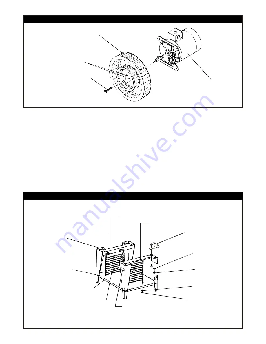
SKETCH “C” - CLEANING THE BLOWER WHEEL
Blower Wheel
Set Screw (2)
Wheel Puller Bolt 3/8” Hex
Motor
SKETCH “D” - OPEN RACK STAND ASSEMBLY INSTRUCTIONS
Rack Support
Label, Restraining Device
for Casters
Open Rack Shelf
30” Legs
3/8”-16 x 3/4” Large
Truss Head Screw
w/Nut & Washer (8)
Top Left Angle
Top Right Angle
Restraining Plate for
Legs w/Casters
½” Flat Washer
(4 Corners Only)
½” - 13 x 1” Large
Hex Head Bolt (12)
5/16” Flat Washer (4)
5/16”-18 Hex Nut (4)
R
T
F
ON
L b
l
a e
Содержание CO1-E
Страница 18: ...NOTES 18 ...


