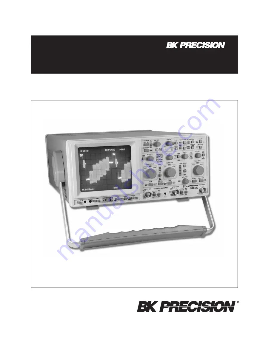
150 MHz (200MS/s) ANALOG/DIGITAL OSCILLOSCOPE
+
INSTRUCTION
MANUAL
MODELS 5105A
¨
Страница 1: ...150 MHz 200MS s ANALOG DIGITAL OSCILLOSCOPE INSTRUCTION MANUAL MODELS 5105A ...
Страница 2: ...nal triggering 31 HOLD OFF time adjustment 31 B time base 2nd time base 31 Triggering after Delay 31 AUTO SET 32 Component Tester analog mode 32 General 32 Using the Component Tester 33 Test Procedure 33 Test Pattern Displays 33 Testing Resistors 33 Testing Capacitors and Inductors 33 Testing Semiconductors 33 Testing Diodes 33 Testing Transistors 34 In Circuit Tests 34 Storage mode 34 Signal reco...
Страница 3: ... meters long If an interface has several connectors only one connector must have a connection to a cable Basically interconnections must have a double shielding 2 Signal cables Basically test leads for signal interconnection between test point and instrument should be as short as possible Without instruction in the manual for a shorter length signal lines must be less than 3 meters long Signal lin...
Страница 4: ......
Страница 5: ...only be inserted in a socket outlet provided with a protective earth contact The protective action must not be negated by the use of an extension cord without a protective conductor The main line plug must be inserted before connec tions are made to measuring circuits The grounded accessible metal parts case sockets jacks and the main line supply contacts line live neutral of the instrument have b...
Страница 6: ...r supply Size 5x20mm 0 8A 250V AC fuse must meet IEC specification 127 Sheet III or DIN 41 662 or DIN 41 571 sheet 3 Time characteristic fast F This fuse must not be replaced by the operator should be kept in a clean and dry room and must not be operated in explosive corrosive dusty or moist environ ments The oscilloscope can be operated in any position but the convection cooling must not be impai...
Страница 7: ...wards at each change Pure direct voltages can only be measured with DC coupling The input coupling is selectable by the AC DC pushbutton The actual setting is displayed in the readout with the symbol for DC and the symbol for AC coupling Amplitude Measurements In general electrical engineering alternating voltage data normally refers to effective values rms root mean square value However for signa...
Страница 8: ...n this case an appropriate high voltage capacitor approx 22 68nF must be connected in series with the input tip of the probe With Y POS control input coupling to GD it is possible to use a horizontal graticule line as reference line for ground potential before the measurement It can lie below or above the horizontal central line according to whether positive and or negative deviations from the gro...
Страница 9: ...at the full height of the signal edge of interest is visible in its full length at not too great steepness and that the horizontal distance at 10 and 90 of the amplitude is measured If the edge shows rounding or over shooting the 100 should not be related to the peak values but to the mean pulse heights Breaks or peaks glitches next to the edge are also not taken into account With very severe tran...
Страница 10: ...ing problems are eliminated Hum or interference appearing in the measuring circuit especially when a small deflection coefficient is used is possibly caused by multiple grounding because equalizing currents can flow in the shielding of the test cables voltage drop between the protective conductor connections caused by external equipment connected to the mains line e g signal generators with interf...
Страница 11: ... and no other LED on the front panel is lit except A All INTENS settings are stored after the instrument is switched off The AUTO SET function switches the readout on and selects A time base mode A LED lit The INTENS setting for each function is automatically set to the mean value if less intensity was previously selected 5 TR The trace rotation control can be adjusted with a small screwdriver ple...
Страница 12: ...ally again it will be required to stop rotating the knob for at least about 2 seconds Attention The dynamic range limits of the A D converter may become visible if a Y position shift is performed after storage This can affect those signal parts which were originally above or below the screen 8 PTR PK Det Pushbutton with two functions Neither function is available in analog mode PTR Briefly pressin...
Страница 13: ... STOR MODE Pushbuttons with associated LEDs These functions are not available in analog mode If digital SINGLE SGL mode has not been chosen one of the associated LEDs is lit The signal capture and display mode can be selected by pressing one of the pushbuttons The mode setting is indicated by one of the LEDs RFR ENV AVM and ROL and also displayed by the readout The only exception is in XY storage ...
Страница 14: ...ng mode on or off SINGLE mode is indicated by the associated SGL LED SINGLE mode is available in digital as well as in analog mode and remains unchanged when switching over from analog to digital mode or vice versa The main purpose of SINGLE is the capture of one time events but it can also be used in combination with repetitive signals SINGLE mode automatically selects A time base mode and normal...
Страница 15: ...utton until a beep confirms reference memory acquisition Before starting the procedure the current signal can but must not be protected by the HOLD function As the reference signal is then equal to the current signal it is usually not visible at once If neither HOLD nor SINGLE is active the current signal can be shifted by the Y POS control s to make the reference signal visible If both REFERENCE ...
Страница 16: ...o determine the DC content of a signal by comparing the actual Y position with the previously determined 0 Volt Y position Y POS I Symbol Provided that the readout is displayed and DC REFE RENCE ON is selected in the SETUP submenu MISCELLANEOUS the 0 Volt reference position is indicated by a ground symbol For channel I this symbol is displayed on the left of the vertical graticule center line if t...
Страница 17: ...rning the control knob causes a different trigger point setting voltage The trigger unit starts the time base when the edge of a trigger signal voltage crosses the trigger point In most Yt modes the trigger point is displayed in the readout by the symbol on the left vertical graticule line If the trigger point symbol would overwrite other readout information or would be invisible when being set ab...
Страница 18: ... GD 34 38 Whether alternated or chopped channel switching is present in analog mode depends on the actual time base setting and is displayed in the readout ALT analog mode only displayed in the readout indicates alternate channel switching After each time base sweep the instrument internally switches over from channel I to channel II and vice versa This channel switching mode is automatically sele...
Страница 19: ...te A B time base mode B time base mode and line mains trigger coupling STORAGE MODE ONLY In ROLL mode the signal capture is untriggered Con sequently alternate triggering is not available 25 VOLTS DIV Control knob This control knob for channel II has a double function The following description relates to the input attenuator function VAR LED dark Turning the control knob clockwise increases the se...
Страница 20: ...start of the intensified sector In the free run condition delay trigger not active of the B time base an approximate value is displayed in the readout Dt This is an aid to find the position of the intensified sector which may be very small If only the B time base is being operated the delay time can be varied but there is no intensified sector as the A trace is not visible STORAGE MODE ONLY The HO...
Страница 21: ... information is also displayed in the readout as an approximate value e g Dt 2 5ms related to the calibrated A time coefficient uncalibrated i e Dt 2 5ms The width of the segment decreases when the B time coefficient is set to a lower value higher time deflection speed Alternate time base mode causes the display to alter between A and B time base after each sweep analog mode In alternate DUAL mode...
Страница 22: ...oefficient setting is not possible in storage mode Underneath the front panel sector described before the BNC sockets and four pushbuttons are located 32 INPUT CH I BNC socket This BNC socket is the signal input for channel I In XY mode signals at this input are used for the Y deflection The outer ground connection is galvanically connected to the instrument ground and consequently to the safety e...
Страница 23: ... there are the controls for the readout the component tester and the square wave calibrator with their outputs Please note The following description of the cursor related controls assumes that the readout is visible and component test is inactive 40 PRINT MENU Pushbutton with 2 functions STORAGE MODE ONLY PRINT Briefly pressing the pushbutton starts a document hardcopy if the following preconditio...
Страница 24: ...ust be activated Briefly pressing the CHI II 1 t ON OFF pushbutton switches from f to t and the following measure ment modes until the readout displays f again In all conditions vertical cursor lines are displayed even if voltage measurements are performed CX Time measurement of the active cursor is related to the trigger point If the active cursor position is on the left of the trigger symbol a n...
Страница 25: ...ed in the readout must be multiplied by 100 if e g a x100 100 1 probe is used In case of x10 10 1 probes the probe factor can be automatically included see AC DC 33 and AC DC 37 t In time or frequency measurement condition two vertical cursor lines are displayed The measurement result is indicated as t time measurement or f frequency measurement Please note item 41 1 Dt NOTE For frequency measurem...
Страница 26: ...evice under test The oscilloscope is switched on by depressing the red POWER pushbutton After a few seconds the B K logo and the instrument software release is displayed on the screen As long as the B K logo is visible different internal checks are made Thereafter the instrument will revert to its last used operating mode If after approx 20 seconds no trace is visible the AUTO SET pushbutton shoul...
Страница 27: ...1MHz Operate the oscilloscope as described under 1kHz but select for 0 2µs div time deflection coefficient setting Insert the probe tip into the output socket A waveform will be displayed on the CRT screen with leading and trailing edges clearly visible For the HF adjustment now to be per formed it will be necessary to observe the rising edge as well as the upper left corner of the pulse top The l...
Страница 28: ... are the same for both channels because the X x10 magnifier is inactive in XY mode The bandwidth of the X amplifier is lower than the Y amplifier and the phase angle which increases with higher frequencies must be taken into account please note data sheet The inversion of the X input signal is not possible Lissajous figures can be displayed in the X Y mode for certain measuring tasks Comparing two...
Страница 29: ...that several cycles of the modulation frequency are visible Strictly speaking triggering should be external with modulation frequency from the AF generator or a demo dulator However internal triggering is frequently possible with normal triggering using a suitable trigger level setting and possibly also using the time vernier variable adjustment Figure 1 Amplitude and frequency spectrum for AM dis...
Страница 30: ...gger coupling setting In the absence of an adequate trigger signal or when the trigger controls particularly the trigger LEVEL control are misadjusted no trace is visible i e the screen completely blanked When using the internal normal triggering mode it is possible to trigger at any amplitude point of a signal edge even with very complex signal shapes by adjusting the trigger LEVEL control If the...
Страница 31: ...xternal trigger voltage itself is displayed first with internal triggering In most cases the composite video signal has a high DC content With constant video information e g test pattern or color bar generator the DC content can be suppressed easily by AC input coupling of the oscilloscope amplifier With a changing picture content e g normal program DC input coupling is recommended because the dis...
Страница 32: ...aiting the trigger pulse This causes an untriggered display and a flashing trigger LED HOLD OFF time adjustment For instrument specific information please note DEL POS HO 28 in section Controls and Readout If it is found that a trigger point cannot be found on extremely complex signals even after careful adjustment of the trigger level control a stable display may often be obtained using the hold ...
Страница 33: ...ly for a display of approx 2 signal periods The time base setting occurs randomly if complex signals consisting several frequencies e g video signals are present AUTO SET sets the instrument automatically to the following operating conditions The input coupling is not affected while AC or DC is used but if GD was selected the last used input coupling AC or DC will be chosen Internal triggering cha...
Страница 34: ...determination of actual values will come with experience or by direct comparison with a component of a known value Testing Capacitors and Inductors Capacitors and inductors cause a phase difference between current and voltage and therefore between the X and Y deflection giving an ellipse shaped display The position and opening width of the ellipse will vary according to the impedance value at 50Hz...
Страница 35: ...ompared with single components In case of doubt one component terminal may be unsoldered This terminal should then not be connected to the ground socket avoiding hum distortion of the test pattern Another way is a test pattern comparison to an identical circuit which is known to be operational likewise without power and any external connections Using the test prods identical test points in each ci...
Страница 36: ...nd Controls Vertical resolution The dot density in each operation mode is 8 bits 28 256 dots displayed over a height of roughly 10 divisions The instrument is adjusted for 25 dots per division This eases processing and cursor measurement Insignificant differences between the analog screen display and the digital data are unavoidable This concerns signal height as well as the position The trace pos...
Страница 37: ...ack must on no never be visible Visible trace faults without input signal bright dot on the left side or decreasing brightness from left to right or shortening of the baseline Cause Incorrect Unblanking Pulse It should be noted that with wide variations in brightness refocusing is always necessary Moreover with maximum brightness no pumping of the dis play must occur If pumping does occur it is no...
Страница 38: ...ting the trimmer located in the 2 1 attenuator The shape of the square wave should then be the same in each input attenuator position Operating Modes CH I II DUAL ADD CHOP INVERT and X Y Operation In DUAL mode two traces must appear immediately On actuation of the Y POS controls the trace positions should have minimal effect on each other Nevertheless this cannot be entirely avoided even in fully ...
Страница 39: ... Then both readout information regarding the time deflection coefficient and the time difference show exactly the same value After switching over from time to frequency measurement the readout displays the required signal frequency in each time base setting Hold Off time Analog The variation of the hold off time setting can not be measured without opening the instrument However a visual check can ...
Страница 40: ... the oscilloscope and the first command SPACE CR 20hex 0Dhex sent from the PC the baud rate is recognized and set automatically between 110 baud and 19200 baud The oscilloscope is then switched over to REMOTE control mode The oscilloscope RS232 Interface Remote Control then transmits the RETURNCODE 0 CR LF to the PC In this status all settings with the exception of those functions mentioned under ...
Страница 41: ... 2001 B K Precision Corp 481 323 9 001 Printed in U S A 1031 Segovia Circle Placentia CA 92870 ...