background image


INSTRUCTION 

MANUAL 


MODEL 1686A 


3 to 14 VOLT  

DC POWER  

SUPPLY 


Содержание 1686A

Страница 1: ...1 INSTRUCTION MANUAL MODEL 1686A 3 to 14 VOLT DC POWER SUPPLY...

Страница 2: ...hazard a If the equipment under test is the hot chassis type a serious shock hazard exists unless the equipment is unplugged just turning off the equipment does not remove the hazard or the precaution...

Страница 3: ...3 Instruction Manual for MODEL 1686A 3 to 14 VOLT DC POWER SUPPLY 22820 Savi Ranch Parkway Yorba Linda California 92887...

Страница 4: ...Power Supply Hook up and Operation 9 Considerations 10 Current Limiting 11 Connecting Two Supplies in Series 11 Connecting Two Supplies in Parallel 11 page MAINTENANCE 14 Fuse Replacement 14 Line Vol...

Страница 5: ...y radios such as CB transceivers VHF UHF commercial equipment marine car telephone and 2 meter transceivers The power supply utilizes thermostatically controlled fan cooling for improved heat dissipat...

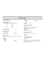
Страница 6: ...voltage Short Circuit METERING Voltmeter Range Accuracy 0 to 20V 7 F S Ammeter Range Accuracy 0 to 20A 7 F S AC Input 115 230 VAC 10 50 60Hz POWER CONSUMPTION 400 W TEMPERATURE RANGE HUMIDITY Operatio...

Страница 7: ...eed 2 amperes 10 Line Cord 11 Fuse 12 Fan 1 POWER Switch Turns power supply on and off Power on indicated by pilot lamp above switch 2 Power ON light Lights when power is turned on 3 OVERLOAD Indicato...

Страница 8: ...8 CONTROLS AND INDICATORS Figure 1 Front Panel Controls and Indicators Model 1686A Figure 2 Rear Panel...

Страница 9: ...Observe all TEST INSTRUMENT SAFETY precautions listed in the front of this manual EQUIPMENT PROTECTION PRECAUTIONS CAUTION The following precautions will help avoid damage to the power supply 1 Avoid...

Страница 10: ...nugly to assure low resistance 2 Connect the red OUTPUT terminal of the power supply to the positive polarity input of the equipment being powered 3 Connect the black OUTPUT terminal of the power supp...

Страница 11: ...provide a variable 6 to 28 volts output The maximum output current will remain at 12 amps See Fig 4 for the connection scheme The voltage is controlled by both VOLTAGE controls and is equal to the sum...

Страница 12: ...12 OPERATING INSTRUCTIONS Figure 4 Connecting Two Power Supplies in Series for a 6 to 28 Volt Output...

Страница 13: ...13 OPERATING INSTRUCTIONS Figure 5 Connecting Two Power Supplies in Parallel for 3 to 14 Volt Output at Double Amperage...

Страница 14: ...e bottom of the chassis To convert to a different line voltage perform the following procedure 1 Make sure the power cord is unplugged 2 Turn the unit over bottom up and reset the LINE VOLTAGE SELECT...

Страница 15: ...14 50 0 10 volts on the multimeter 4 Set the power supply front panel VOLTAGE control for a reading of 14 00 0 10 volts on the multimeter 5 Adjust Trimmer VR4 so that the meter pointer on the V meter...

Страница 16: ...tive load for a reading of 15 amps on the unit s A meter scale 8 Adjustable Trimmer VR2 clockwise unit the output voltage read on the multimeter drops by 0 05 to 0 20 V INSTRUMENT REPAIR SERVICE Becau...

Страница 17: ...ccount must include payment in the form of a money order or credit card For the most current repair charges please visit www bkprecision com and click on service repair Return all merchandise to B K P...

Страница 18: ...nstrument via our website www bkprecision com Exclusions This warranty does not apply in the event of misuse or abuse of the product or as a result of unauthorized alterations or repairs The warranty...

Страница 19: ...et is removed for servicing a serious shock hazard exists if the chassis is touched Not only does this present a dangerous shock hazard but damage to test instruments or the equipment under test may r...

Страница 20: ...20 B K Precision Corporation 22820 Savi Ranch Parkway Yorba Linda California 92887 www bkprecision com 2014 B K Precision Corporation 481 370 9 001 Printed in China V043014...

Отзывы: