background image

EN

2

Table of contents


Page

1. 

Introduction 


3

2. 

Safety 


3-5

3. 

Controls and Jacks    


 5

4. 

Symbols and Annunciators  


 6

5. 

Operating Instructions   


 7

5-1. 

DC Voltage Measuments  


 7

5-2. 

AC Voltage (Frequency, Duty Cycle) Measurements  

 8

5-3. 

MV Voltage Measurements  


 9

5-4. 

DC Current Measurements  


 10

5-5. 

AC Current (Frequency, Duty Cycle) Measurements  

 11

5-6. 

Resistance Measurements  


 12

5-7. 

Continuty Check  


 12

5-8. 

Diode 

Test 


13

5-9. 

Temperature Measurements  


 13

5-10. 

Frequency / Duty Cycle Measurements (Electronic) 

 14

5-11. 

Autoranging / Manual Range Selection  


 14

5-12. 

MAX/MIN 


14

5-13. 

Relative 

Mode 


15

5-14. 

Display Backlight  


 15

5-15. 

HOLD 


15

5-16. 

AUTO Power Off  


 15

5-17. 

LOW Battery Indication  


 15

6. 

Maintenance 


16

6-1. 

Battery Installation  


 17

6-2. 

Replacing the Fuses    


 17

7. 

Specifications  


 18-21

Exe_Notice_BIZ780312_EN-FR-NL.indd   2

15/05/2019   17:37

Содержание BIZ 780 312

Страница 1: ...oded emploi p 22 Lisez ce manuel avant d utiliser l appareil Informations importantes de sécurité à l intérieur NL DIGITALE MULTIMETER Gebruiksaanwijzing p 42 Lees deze gebruiksaanwijzing voordat u het apparaat inschakelt Belangrijke veiligheidsinformatie binnenin BIZ 780 312 SE E nr 42 023 20 Snro 67 045 07 e_Notice_BIZ780312_EN FR NL indd 1 15 05 2019 17 3 ...

Страница 2: ...Duty Cycle Measurements 11 5 6 Resistance Measurements 12 5 7 Continuty Check 12 5 8 Diode Test 13 5 9 Temperature Measurements 13 5 10 Frequency Duty Cycle Measurements Electronic 14 5 11 Autoranging Manual Range Selection 14 5 12 MAX MIN 14 5 13 Relative Mode 15 5 14 Display Backlight 15 5 15 HOLD 15 5 16 AUTO Power Off 15 5 17 LOW Battery Indication 15 6 Maintenance 16 6 1 Battery Installation ...

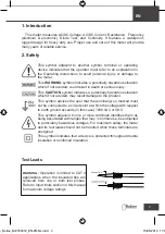
Страница 3: ...tion which if not avoided may result damage to the product This symbol advises the user that the terminal s so marked must not be connected to a circuit point at which the voltage with respect to earth ground exceeds in this case 1000 VAC or VDC This symbol adjacent to one or more terminals identifies them as being associated with ranges that may in normal use be subjected to particularly hazardou...

Страница 4: ...tage or current to the meter that exceeds the specified maximum Input Protection Limits Function Maximum Input VDC 1000 VDC RMS VCA 1000 VAC RMS mA AC DC 800 mA 1000 V fast acting fuse A AC DC 10 A 1000 V fast acting fuse 30 seconds max every 15 minutes Frequency resistance CAP diode test de continuity 250 VDC AC RMS Surge Protection 8 kV peak per IEC 61010 e_Notice_BIZ780312_EN FR NL indd 4 15 05...

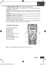
Страница 5: ... the test leads before opening the covers to replace the fuse or batteries 7 NEVER operate the meter unless the back cover and the battery and fuse covers are in place and fastened securely 8 If the equipment is used in a manner not specified by the manufacturer the proctection provided by the equipment may be impaired 3 Controls and Jacks 1 6000 counts LCD display 2 MAX MIN button 3 RANGE button ...

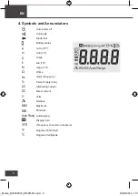
Страница 6: ...lo 103 mega 106 Ohms Hertz frequency Percent duty ratio Alternating current Direct current Volts Relative Maximum Minimum Autoranging Display hold Frequency conversion measure Degrees Fahrenheit Degrees Centigrade µ m A k M Ω Hz AC DC V MAX MIN Auto Rang VFD ºF ºC e_Notice_BIZ780312_EN FR NL indd 6 15 05 2019 17 3 ...

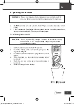
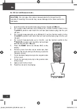
Страница 7: ... on the circuit is being switched ON or OFF Large voltage surges may occur that can damage the meter 1 Set the function switch to the V position 2 Insert the black test lead banana plug into the negative COM jack 3 Insert the red test lead banana plug into the positive V jack 4 Touch the black test probe tip to the negative side of the circuit 5 Touch the red test probe tip to the positive side of...

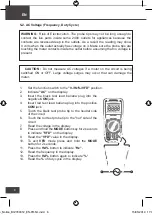
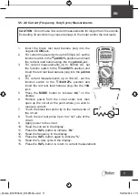
Страница 8: ... AC on the display 3 Insert the black test lead banana plug into the negative COM jack 4 Insert red test lead banana plug into the positive COM jack 5 Touch the black test probe tip to the neutral side of the circuit 6 Touch the red test probe tip to the hot side of the circuit 7 Read the voltage in the display 8 Press and hold the MODE button key for 2 seconds to indicate VFD on the display 9 Rea...

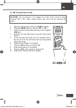
Страница 9: ...ition 2 Press the MODE button to indicate DC or AC 3 Insert the black test lead banana plug into the negative COM jack 4 Insert the red test lead banana plug into the positive V jack 5 Touch the black test probe tip to the negative side of the circuit Touch the red test probe tip to the positive side of the circuit 6 Read the mV voltage in the display 7 Press the HZ button to indicate Hz 8 Read th...

Страница 10: ... switch to the mA HZ position and insert the red test lead banana plug into the µA mA jack 4 For current measurements up to 10A DC set the function switch to the 10A HZ position and insert the red test lead banana plug into the 10A jack 5 Press the MODE button to indicate DC on the display 6 Remove power from the circuit under test then open up the circuit at the point where you wish to measure cu...

Страница 11: ...e 10A HZ position and insert the red test lead banana plug into the 10A jack 5 Press the MODE button to indicate AC on the display 6 Remove power from the circuit under test then open up the circuit at the point where you wish to measure current 7 Touch the black test probe tip to the neutral side of the circuit 8 Touch the red test probe tip to the hot side of the circuit 9 Apply power to the cir...

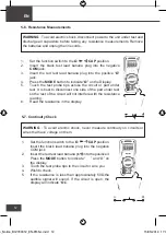
Страница 12: ... display 5 7 Continuity Check WARNING To avoid electric shock never measure continuity on circuits or wires that have voltage on them 1 Set the function switch to the Ω CAP position Insert the black lead banana plug into the negative COM jack 2 Insert the red test lead banana plug into the positive3 Press the MODE button to indicate and Ω on the display 3 Touch the test probe tips to the circuit o...

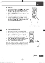
Страница 13: ...input jacks making sure to observe the correct polarity 3 Press the MODE button to indicate ºF or ºC 4 Touch the Temperature Probe head to the part whose temperature you wish to measure 5 Keep the probe touching the part under test until the Reading stabilizes about 30 seconds 6 Read the temperature in the display Note The temperature probe is fitted with a type K mini connector A mini connector t...

Страница 14: ... available ranges until you select the range you want 3 To exit the Manual Ranging mode and return to Autoranging press and hold the RANGE key for 2 seconds Note Manual ranging does not apply for the Frequency functions 5 12 MAX MIN Note When using the MAX MIN function in Autoranging mode the meter will lock into the range that is displayed on the LCD when MAX MIN is activated If a MAX Min reading...

Страница 15: ... REL button to exit the relative mode Note The Relative function does not operate in the Frequency function 5 14 Display Backlight Press and hold the HOLD key for 1 second to turn on or off the display backlight function The backlight will automatically turn off after 5 minutes 5 15 HOLD The hold function freezes the reading in the display Press the HOLD key momentarily to activate or to exit the ...

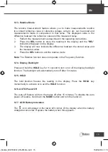
Страница 16: ...SE AND STORE THE METER IN NORMAL TEMPERATURES Temperature extremes can shorten the life of the electronic parts and distort or melt plastic parts 3 HANDLE THE METER GENTLY AND CAREFULLY Dropping it can damage the electronic parts or the case 4 KEEP THE METER CLEAN Wipe the case occasionally with a damp cloth DO NOT use chemicals cleaning solvents or detergents 5 USE ONLY FRESH BATTERIES OF THE REC...

Страница 17: ...r does not work properly check the fuses and batteries to make sure that they are still good and that they are properly inserted 6 2 Replacing the Fuses WARNING To avoid electric shock disconnect the test leads from any source of voltage before removing the fuse cover 1 Disconnect the test leads from the meter 2 Remove the battery cover 3 Gently remove the old fuse and install the new fuse into th...

Страница 18: ... 9 digits 600 0 mV 0 1 mV 0 8 reading 3 digits 6 000 V 0 001 V 60 00 V 0 01 V 600 0 V 0 1 V 1000 V 1 V 0 8 reading 8 digits All AC Voltage ranges are specified from 5 of range to 100 of range VFD 50 0 V 700 V 0 1 V 1 V 4 reading 3 digits DC Current 600 0 µA 0 1 µA 1 0 reading 3 digits 6000 µA 1 µA 60 00 mA 0 01 mA 600 0 mA 0 1 mA 6 000 A 0 001 A 1 5 reading 3 digits 10 00 A 0 01 A 10 A 30 sec max ...

Страница 19: ...ange to 100 of range Function Range Resolution Accuracy Resistance 600 00 Ω 0 10 Ω 1 0 reading 2 digits 6 000 kΩ 0 001 kΩ 0 8 reading 2 digits 60 00 kΩ 0 01 kΩ 600 0 kΩ 0 1 kΩ 6 000 MΩ 0 001 MΩ 1 2 reading 2 digits 60 00 MΩ 0 01 MΩ 1 0 reading 5 digits Capacity 99 99 nF 0 01 nF 4 0 reading 5 digits 999 9 nF 0 1 nF 9 999 µF 0 001 µF 99 99 µF 0 01 µF 999 9 µF 0 1 µF 9 999 mF 0 001 mF 10 reading 99 9...

Страница 20: ... ms Frequency 5 Hz to 150 kHz T e m p type K 40 à 1832 F 0 1 F 3 0 reading 3 C 5 F dogits probe accuracy not included 40 à 1000 C 0 1 C NOTE Accuracy specifications consist of two elements reading This is the accuracy of the measurement circuit digits This is the accuracy of the analog to digital converter NOTE Accuracy is stated at 18 C to 28 C 65 F to 83 F and less than 75 RH Enclosure Double in...

Страница 21: ... blow A range 10 A 1000 V ceramic fast blow Operating Temperature 5 C to 40 C 41 F to 104 F Storage Temperature 20 C to 60 C to 140 F Operating Humidity Max 80 up to 31 C 87 F decreasing linearly to 50 at 40 C 104 F Storage Humidity 80 Operation Altitude 7000ft 2000 meters maximum Weight 436 g includes holster Size 182 x 82 x 59 mm boîtier compris Safety This meter is intended for origin of instal...

Страница 22: ...esures de résistance 32 5 7 Contrôle de continuité 32 5 8 Test de diode 33 5 9 Mesures de température 33 5 10 Mesures de fréquence cycle opératoire électronique 34 5 11 Sélection de gamme automatique manuelle 34 5 12 MAX MIN 34 35 5 13 Mode mesure relative 35 5 14 Rétroéclairage de l écran 35 5 15 HOLD Maintien des données 35 5 16 Mise hors tension automatique 35 5 17 Indication pile faible 35 6 M...

Страница 23: ...Ce symbole avertit l utilisateur que les bornes ainsi marquées ne peuvent pas être connectées à un point du circuit où la tension par rapport à la terre est supérieure dans ce cas précis à 1000 VCA ou VCC Ce symbole apposé à proximité d une ou plusieurs bornes signifie qu elles sont associées à des gammes qui en utilisation normale peuvent être soumises à des tensions très dangereuses Pour assurer...

Страница 24: ...ur l appareil une tension ou un courant supérieurs aux valeurs maximales spécifiées Limites de protection d entrée Fonction Entrée maximale VCC 1000 VCC RMS VCA 1000 VCA RMS mA CA CC 800 mA 1000 V fusible rapide A CA CC 10 A 1000 V fusible rapide 30 secondes max toutes les 15 minutes Fréquence résistance capacité essai de diode de continuité 250 VCC CA RMS Protection contre les surtensions 8 kV cr...

Страница 25: ...reil et débranchez les fils d essai avant d ouvrir les compartiments pour remplacer les piles 7 N utilisez JAMAIS l appareil si les compartiments à piles et fusibles ne sont pas correctement verrouillés 8 Si vous utilisez l équipement selon des modalités non spécifiées par le fabricant la protection qu il assure peut être compromise 3 Commandes et bornes 1 Écran LCD 6000 mesures 2 Touche MAX MIN 3...

Страница 26: ...106 Ohms Hertz fréquence Pourcentage facteur cycle opératoire Courant alternatif Courant continu Volts Relative Maximum Minimum Sélection de gamme automatique Maintien de l affichage mesure de conversion de fréquence Degrés Fahrenheit Degrés Celsius µ m A k M Ω Hz AC DC V MAX MIN Auto Rang VFD ºF ºC e_Notice_BIZ780312_EN FR NL indd 26 15 05 2019 17 3 ...

Страница 27: ...n moteur est en cours de mise SOUS ou HORS tension sur le circuit D importantes surtensions peuvent se produire et endommager l appareil 1 Positionnez le sélecteur de fonctions sur V 2 Branchez la fiche banane du fil d essai noir sur la borne négative COM 3 Branchez la fiche banane du fil d essai rouge sur la borne positive V 4 Posez la pointe de la sonde d essai noire sur le côté négatif du circu...

Страница 28: ...iche banane du fil de test noir dans la borne négative COM 4 Introduisez la fiche banane du fil de test rouge dans la borne positive V 5 Posez la pointe de la sonde d essai noire sur le côté neutre du circuit 6 Posez la pointe de la sonde d essai rouge sur le côté chaud du circuit 7 L écran affiche la tension mesurée 8 Appuyez sur la touche MODE et maintenez la enfoncée pendant 2 secondes jusqu à ...

Страница 29: ...cran affiche DC ou AC 3 Introduisez la fiche banane du fil de test noir dans la borne négative COM Introduisez la fiche banane du fil de test rouge dans la borne positive V 4 Posez la pointe de la sonde d essai noire sur le côté négatif du circuit Posez la pointe de la sonde d essai rouge sur le côté positif du circuit 5 L écran affiche la tension mV mesurée 6 Appuyez sur la touche Hz jusqu à ce q...

Страница 30: ...sélecteur de fonction sur mA Hz et branchez la fiche banane du fil d essai rouge sur la borne µA mA 4 Pour des mesures de courant allant jusqu à 10 A CC positionnez le sélecteur de fonction sur 10A Hz et branchez la fiche banane du fil d essai rouge sur la borne 10A 5 Appuyez sur la touche MODE jusqu à ce que l écran affiche DC 6 Coupez l alimentation du circuit testé puis ouvrez le circuit au poi...

Страница 31: ... A Hz et introduisez la fiche banane du fil d essai rouge dans la borne 10A 5 Appuyez sur la touche MODE jusqu à ce que l écran affiche CA 6 Coupez l alimentation du circuit testé puis ouvrez le circuit au point où vous voulez mesurer le courant 7 Posez la pointe de la sonde d essai noire sur le côté neutre du circuit 8 Posez la pointe de la sonde d essai rouge sur le côté chaud du circuit 9 Mette...

Страница 32: ... affiche la résistance mesurée 5 7 Contrôle de continuité AVERTISSEMENT Pour éviter tout choc électrique ne mesurez jamais la continuité sur des circuits ou des cordons sous tension 1 Positionnez le sélecteur de fonctions sur Ω CAP 2 Introduisez la fiche banane du fil d essai noir dans la borne négative COM 3 Introduisez la fiche banane du fil d essai rouge dans la borne positive O 4 Appuyez sur l...

Страница 33: ...z la sonde de température dans la borne d entrée en respectant la polarité 3 Appuyez sur la touche MODE jusqu à ce que l écran affiche F ou C 4 Appliquez la pointe de la sonde de température sur la partie dont vous souhaitez mesurer la température Maintenez la sonde en contact jusqu à stabilisation de la mesure pendant environ 30 secondes 5 L écran affiche la température mesurée Remarque La sonde ...

Страница 34: ... sélection manuelle de la gamme suivez la procédure suivante 1 Appuyez sur la touche RANGE L indication AUTO disparaît 2 Appuyez plusieurs fois sur la touche RANGE pour visualiser les gammes disponibles et sélectionnez celle qui vous convient 3 Pour quitter le mode Sélection de gamme manuelle et retourner au mode Sélection de gamme automatique appuyez sur la touche RANGE et maintenez la enfoncée p...

Страница 35: ...cran affiche ensuite la différence entre la valeur de enregistrée et la valeur mesurée Appuyez sur la touche REL pour quitter le mode de mesure relative Remarque La fonction de mesure relative n est pas disponible pour la fonction Fréquence 5 14 Rétroéclairage de l écran Appuyez sur la touche HOLD et maintenez pendant plus d 1 seconde pour CAtiver ou désactiver la fonction rétroéclairage de l écra...

Страница 36: ...S NORMALES L utilisation de l appareil à des températures extrêmes peut raccourcir la durée de vie des composants électroniques et déformer ou faire fondre les pièces en plastique 3 MANIPULEZ L APPAREIL EN DOUCEUR ET AVEC PRECAUTION Une chute de l appareil peut endommager les composants électroniques ou le boîtier de l appareil 4 MAINTENEZ L APPAREIL PROPRE Nettoyez régulièrement le boîtier de l a...

Страница 37: ...érifiez que les fusibles et la pile sont en état de fonctionnement et qu ils sont correctement insérés 6 2 Remplacement des fusibles AVERTISSEMENT Pour éviter tout choc électrique débranchez les fils d essai de toute source de tension avant de déposer le capot du compartiment à fusibles Débranchez les fils d essai de l appareil Déposez le capot du compartiment à piles Retirez doucement l ancien fu...

Страница 38: ...9 9 chiffres 600 0 mV 0 1 mV 0 8 3 chiffres 6 000 V 0 001 V 60 00 V 0 01 V 600 0 V 0 1 V 1000 V 1 V 0 8 8 chiffres Toutes les gammes de tension CA sont spécifiées de 5 à 100 de la gamme VFD 50 0 V 700 V 0 1 V 1 V 4 3 chiffres Courant CC 600 0 µA 0 1 µA 1 0 3 chiffres 6000 µA 1 µA 60 00 mA 0 01 mA 600 0 mA 0 1 mA 6 000 A 0 001 A 1 5 3 chiffres 10 00 A 0 01 A 10 A 30 s max avec précision réduite e_N...

Страница 39: ...t spécifiées de 5 à 100 de la gamme Fonction Gamme Résolution Précision Résistance 600 00 Ω 0 10 Ω 1 0 2 chiffres 6 000 kΩ 0 001 kΩ 0 8 2 chiffres 60 00 kΩ 0 01 kΩ 600 0 kΩ 0 1 kΩ 6 000 MΩ 0 001 MΩ 1 2 2 chiffres 60 00 MΩ 0 01 MΩ 1 0 5 chiffres Capacité 99 99 nF 0 01 nF 4 0 5 chiffres 999 9 nF 0 1 nF 9 999 µF 0 001 µF 99 99 µF 0 01 µF 999 9 µF 0 1 µF 9 999 mF 0 001 mF 10 99 99 mF 0 01 mF 9 999 nF ...

Страница 40: ...z 40 à 1832 F 0 1 F 3 0 3 C 5 F chiffres hors précision de la sonde 40 à 1000 C 0 1 C Remarque Les spécifications de précision comportent deux éléments Il s agit de la précision du circuit de mesure chiffres Il s agit de la précision du convertisseur digital analogique REMARQUE La précision est définie de 18 C à 28 C 65 F à 83 F avec humidité relative 75 Boîtier Moulage double injection Étanchéité...

Страница 41: ...ue à fusion rapide Gamme A 10 A 1000 V en céramique à fusion rapide Température de fonctionnement De 5 C à 40 C de 41 F à 104 F Température de stockage De 20 C à 60 C de 4 F à 140 F Humidité de fonctionnement 80 max jusqu à 31 C 87 F diminue linéairement à 50 à 40 C 104 F Humidité de stockage 80 Altitude de fonctionnement 2000 mètres 7000 pieds maximum Poids 436 g boîtier compris Dimensions 182 x ...

Страница 42: ...bedrijfscyclusmetingen 51 5 6 Weerstandsmetingen 52 5 7 Continuïteitscontrole 52 5 8 Diodetest 53 5 9 Temperatuurmetingen 53 5 10 Frequentie bedrijfscyclusmetingen elektronisch 54 5 11 Autoranging handmatige selectie van het bereik 54 5 12 MAX MIN 55 5 13 Relatieve modus 55 5 14 Schermachtergrondverlichting 55 5 15 VASTHOUDEN 55 5 16 Automatische uitschakeling 56 5 17 Indicatie van bijna lege batt...

Страница 43: ...uiker erop dat de zo gemarkeerde terminal s niet aangesloten mogen worden op een circuitpunt waar de spanning met betrekking tot de aarding in dit geval meer dan 1000 VAC of VDC bedraagt Dit symbool in de buurt van een of meerdere terminals identificeert deze als een terminal s die is zijn verbonden met bereiken die bij normaal gebruik kunnen worden blootgesteld aan bijzonder gevaarlijke spanninge...

Страница 44: ...pecificeerde maximum overschrijdt Ingangsbeveiligingslimieten Functie Maximale ingang V gelijkspanning 1000 V gelijkspanning RMS V wisselspanning 1000 V wisselspanning RMS mA wissel gelijkspanning Snelle zekering van 800 mA 1000 V A wissel gelijkspanning Snelle zekering van 10 A 1000 V 30 seconden max om de 15 minuten Frequentie weerstand CAP diodetest continuïteit 250 V gelijk wisselspanning RMS ...

Страница 45: ...s opent om de zekering of de batterijen te vervangen 7 Gebruik de meter ALLEEN wanneer het deksel op de achterzijde en het batterij en zekeringdeksel zijn geplaatst en stevig zijn vastgemaakt 8 Als de apparatuur wordt gebruikt op een manier die niet wordt gepreciseerd door de fabrikant kan dat afbreuk doen aan de beveiliging die de apparatuur biedt 3 Bedieningselementen en aansluitingen 1 Lcd sche...

Страница 46: ...père kilo 103 mega 106 Ohm Hertz frequentie Procent inschakelfactor Wisselstroom Gelijkstroom Volt Relatief Maximum Minimum Autoranging Vasthouden van het scherm frequentieconversiemeting Graden Fahrenheit Graden Celsius µ m A k M Ω Hz AC DC V MAX MIN Auto Rang VFD ºF ºC e_Notice_BIZ780312_EN FR NL indd 46 15 05 2019 17 3 ...

Страница 47: ...een motor op de stroomkring wordt in of uitgeschakeld Er kunnen zich hoge stootspanningen voordien die de meter kunnen beschadigen 1 Zet de functieschakelaar in de stand V 2 Stop de zwarte banaanstekker van het testsnoer in de negatieve aansluiting COM 3 Stop de rode banaanstekker van het testsnoer in de positieve aansluiting V 4 Plaats de zwarte testsondepunt op de negatieve zijde van de stroomkr...

Страница 48: ...functieschakelaar in de stand V Hz VFD AC wordt weergegeven op het scherm 2 Stop de zwarte banaanstekker van het testsnoer in de negatieve aansluiting COM Stop de rode banaanstekker van het testsnoer in de positieve aansluiting V 3 Plaats de zwarte testsondepunt op de neutrale zijde van de stroomkring Plaats de rode testsondepunt op de warme zijde van de stroomkring 4 Lees de spanning op het scher...

Страница 49: ...anaanstekker van het testsnoer in de positieve aansluiting V 4 Plaats de zwarte testsondepunt op de negatieve zijde van de stroomkring Plaats de rode testsondepunt op de positieve zijde van de stroomkring 5 Lees de mV spanning op het scherm 6 Druk op de knop Hz om Hz weer te geven 7 Lees de frequentie op het scherm 8 Druk nogmaals op de knop Hz om weer te geven Lees het bedrijfscyclus op het scher...

Страница 50: ... gelijkstroom in de stand mA Hz en stop de rode banaanstekker van het testsnoer in de aansluiting µA mA 4 Zet de functieschakelaar voor stroommetingen tot 10 A gelijkstroom in de stand 10A Hz en stop de rode banaanstekker van het testsnoer in de aansluiting 10A 5 Druk op de knop MODUS om DC op het scherm weer te geven 6 Schakel de stroomtoevoer naar de geteste stroomkring uit en open de stroomkrin...

Страница 51: ...A Hz en stop de rode banaanstekker van het testsnoer in de aansluiting µA mA 4 Zet de functieschakelaar voor stroommetingen tot 10 A wisselstroom in de stand 10A Hz en stop de rode banaanstekker van het testsnoer in de aansluiting 10A 5 Druk op de knop MODUS om AC op het scherm weer te geven 6 Schakel de stroomtoevoer naar de geteste stroomkring uit en open de stroomkring op het punt waar u de str...

Страница 52: ...et scherm weer te geven 4 Plaats de testsondepunten op de geteste stroomkring of het geteste onderdeel U kunt het best één zijde van het geteste onderdeel loskoppelen zodat de rest van de stroomkring niet zal interfereren met de weerstandsmeting 5 Lees de weerstand op het scherm 5 7 Continuïteitscontrole WAARSCHUWING om elektrische schokken te vermijden mag u de continuïteit nooit meten op stroomk...

Страница 53: ... V V 10A mA A Au to Powe r Off 8 Temp VFD RANGE MAX MIN REL HZ MODE HOLD VFD TRUE RMS Autoranging Digital Multimeter CAP V Tem p C F OFF V V 10A mA A Au to Powe r Off 8 Temp VFD RANGE MAX MIN REL HZ MODE HOLD VFD TRUE RMS Autoranging Digital Multimeter CAP V Tem p C F 5 8 Diodetest 1 Zet de functieschakelaar in de stand Ω CAP 2 Stop de zwarte banaanstekker van het testsnoer in de negatieve aanslui...

Страница 54: ...herm 5 11 Autoranging handmatige selectie van het bereik Zodra de meter is ingeschakeld werkt hij automatisch in Autoranging Deze modus selecteert automatisch het beste bereik voor de uitgevoerde metingen en is het over het algemeen de beste modus voor de meeste metingen Ga als volgt te werk voor meetsituaties waarbij een bereik handmatig moet worden geselecteerd 1 Druk op de toets RANGE De scherm...

Страница 55: ... biedt u de mogelijkheid om metingen in vergelijking met een opgeslagen referentiewaarde uit te voeren Een referentiespanning stroom enz kan worden opgeslagen en er kunnen metingen in vergelijking met die waarde worden uitgevoerd De weergegeven waarde is het verschil tussen de referentiewaarde en de gemeten waarde 1 Voer de meting uit in overeenstemming met de beschrijving in de bedieningsinstruct...

Страница 56: ...meter is ontworpen om jarenlang betrouwbaar dienst te doen als de volgende onderhoudsinstructies worden gevolgd 1 HOUD DE METER DROOG Wordt het apparaat nat veeg het dan droog 2 GEBRUIK EN BEWAAR DE METER BIJ NORMALE TEMPERATUREN Extreme temperaturen kunnen de levensduur van de elektronische onderdelen verkorten en plastic onderdelen vervormen of doen smelten 3 BEHANDEL DE METER VOORZICHTIG EN BEH...

Страница 57: ...en batterijen om u ervan te vergewissen dat ze nog altijd goed zijn en juist zijn geplaatst 6 2 De zekeringen vervangen WAARSCHUWING om elektrische schokken te vermijden moet u de testsnoeren van elke spanningsbron loskoppelen voordat u het zekeringdeksel verwijdert 1 Koppel de testsnoeren van de meter los 2 Verwijder het batterijdeksel en de batterij 3 Verwijder voorzichtig de oude zekering en in...

Страница 58: ...600 0 mV 0 1 mV waarde 0 8 3 cijfers 6 000 V 0 001 V 60 00 V 0 01 V 600 0 V 0 1 V 1000 V 1 V waarde 0 8 8 cijfers Alle wisselspanningsbereiken worden gespecificeerd van een bereik van 5 tot een bereik van 100 VFD 50 0 V 700 V 0 1 V 1 V waarde 4 3 cijfers Gelijks troom 600 0 µA 0 1 µA waarde 1 0 3 cijfers 6000 µA 1 µA 60 00 mA 0 01 mA 600 0 mA 0 1 mA 6 000 A 0 001 A waarde 1 5 3 cijfers 10 00 A 0 0...

Страница 59: ...ereik van 5 tot een bereik van 100 Functie Bereik Resolutie Nauwkeurigheid Weerstand 600 00 Ω 0 10 Ω waarde 1 0 2 cijfers 6 000 kΩ 0 001 kΩ waarde 0 8 2 cijfers 60 00 kΩ 0 01 kΩ 600 0 kΩ 0 1 kΩ 6 000 MΩ 0 001 MΩ waarde 1 2 2 cijfers 60 00 MΩ 0 01 MΩ waarde 1 0 5 cijfers Elektrische capaciteit 99 99 nF 0 01 nF waarde 4 0 5 cijfers 999 9 nF 0 1 nF 9 999 µF 0 001 µF 99 99 µF 0 01 µF 999 9 µF 0 1 µF 9...

Страница 60: ... 150 kHz 40 tot 1832 F 0 1 F waarde 3 0 cijfers 3 C 5 F exclusief sondenauwkeurigheid 40 tot 1000 C 0 1 C Opmerking nauwkeurigheidsspecificaties bestaan uit twee elementen waarde dit is de nauwkeurigheid van de meetstroomkring cijfers dit is de nauwkeurigheid van de analoog digitaalomzetter OPMERKING nauwkeurigheid is vastgesteld op 18 C tot 28 C 65 F tot 83 F en minder dan 75 RV Behuizing Dubbel ...

Страница 61: ... van 0 8 A 1000 V A bereik keramische zekering van 10 A 1000 V Bedrijfstemperatuur 5 C tot 40 C 41 F tot 104 F Opslagtemperatuur 20 C tot 60 C 4 F tot 140 F Bedrijfsvochtigheid Max 80 bij maximaal 31 C 87 F met een lineaire daling tot 50 bij 40 C 104 F Opslagvochtigheid 80 Bedrijfshoogte Maximaal 2000 meter 7000 voet Gewicht 436 g inclusief holster Afmetingen 182 x 82 x 59 mm inclusief holster Vei...

Страница 62: ...BIZLINE SAS PARIS FRANCE www bizline com e_Notice_BIZ780312_EN FR NL indd 62 15 05 2019 17 3 ...

Отзывы: