


◈
Information
This installation guide contains only simple information required for the installation of the
product. Refer to the User’s Manual in the CD that is shipped with the product for detailed
instructions for installation. The contents contained in the CD are as follows.
1. Manual: User’s Manual, Code Table, Control Commands, Software manuals
2. Driver: Windows Driver, OPOS, JPOS, CUPS(Linux, Mac), VCOM(USB, Ethernet)
3. SDK: UPOS SDK(iOS, Android)
4. Utility: Unified POS Utility, Net Configuration Tool, Android Utility, iOS Utility
We at Bixolon Co., Ltd. constantly strive to improve product functions and quality. To do
this, the specifications of our product and the contents of the manual may change without
prior notice.
◈
Components
SRP-380/382
Cable Cover
Roll Paper
Procuct Installation CD
Procuct Installation CD
Procuct Installation CD
CD
AC/DC Adaptor
Power Cord
Installation Guide
◈
Cable Connection
1. Turn off the printer and POS System(host computer).
2. Connect the power cord to adaptor, and connect the adapter to the power connector of the
printer.
3. Check the type interface located at the back of the printer(Serial, Dual Serial, Ethernet,
USB, Powered USB, Wireless LAN, Bluetooth) and connect proper cable.
4. Connect the drawer kick-out cable to the drawer kick-out connector located in the back of
the printer.
※
Do not use an adapter that was not supplied with the printer.
◈
Installing Paper Roll
1. Press the Cover-Open button to open the cover.
2. Insert new roll paper in the correct direction.
3. Pull the paper out slightly and close the cover.
※
Note
Hold down the center of the cover firmly when
closing the cover so that the paper maintains close
contact with the roller.
Printing quality may not be optimum if
recommended paper is not used.
(Refer to the User's Manual.)
◈
Paper Jam
(Refer to 1-8 in User’s Manual)
1. Turn the printer off and on, open the cover, and remove the paper.
2. If the cover cannot be opened, turn off the printer, separate the cover-cutter, and try to turn
the auto cutter knob to open the cover.
◈
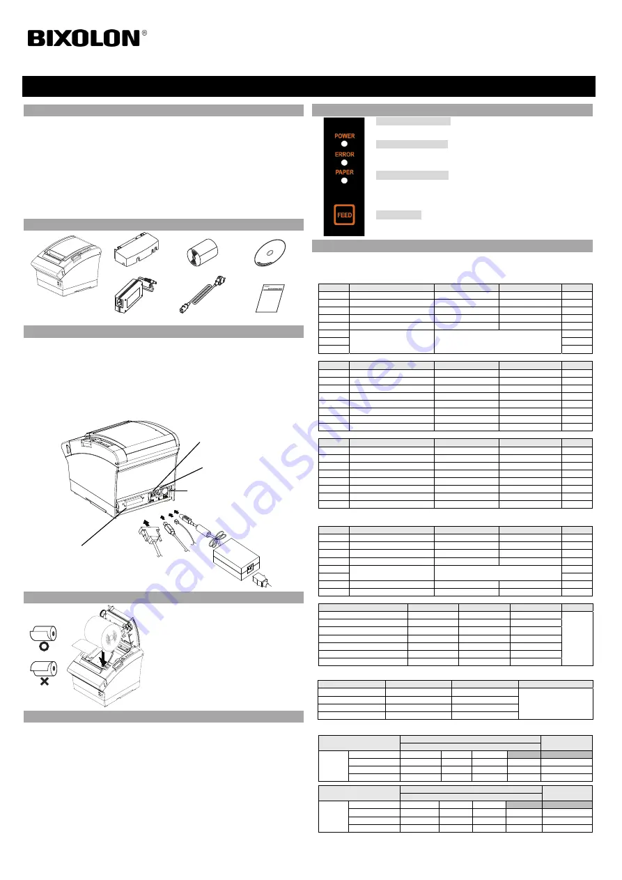
Using Control Panel
•
Power (Indicator Lamp)
Green light will be on when power is supplied to printer.
•
Error (Indicator Lamp)
Red light will be on in various error conditions such as out of paper,
cover open, etc.
•
Paper (Indicator Lamp)
Red light will be on when there is no paper or paper almost runs out. If
this light keeps blinking, it means that the printer is in self-test standby
state or waiting for macro execution.
•
Feed (Button)
Press this button to feed the paper out. Hold down this button to feed
out the paper continuously.
◈
Setting DIP Switches
DIP switch settings should be changed when the printer power is turned off. Any changes made
while printer power is on are not recognized.
1. DIP Switch 1
• Serial
/ Dual Serial Interface Settings
Switch
Function
ON
OFF
Default
1-1
Auto Line Feed
Enabled
Disabled
OFF
1-2 Flow
Control XON/XOFF DTR/DSR
OFF
1-3 Data
Length
7-bit
8-bit OFF
1-4 Parity
Check
Yes
No OFF
1-5 Parity
Selection
EVEN
ODD OFF
1-6
Baud Rate Selection (bps)
Refer to the following Table 1
OFF
1-7
ON
1-8
OFF
•
USB / Ethernet / Wireless LAN / Powered USB interface settings
Switch
Function
ON
OFF
Default
1-1
Auto Line Feed
Enabled
Disabled
OFF
1-2 Reserved
-
- OFF
1-3 Reserved
-
- OFF
1-4 Reserved
-
- OFF
1-5 Reserved
-
- OFF
1-6 Reserved
-
- OFF
1-7 Reserved
-
- ON
1-8 Reserved
-
- OFF
• Bluetooth Interface settings
Switch
Function
ON
OFF
Default
1-1
Auto Line Feed
Enabled
Disabled
OFF
1-2 Reserved
-
- OFF
1-3 SSP
Mode
Enabled Disabled
OFF
1-4 Reserved
-
- OFF
1-5 Reserved
-
- OFF
1-6 Reserved
-
- OFF
1-7 Reserved
-
- ON
1-8 Reserved
-
- OFF
2. DIP Switch 2
• All Interface Settings
Switch
Function
ON
OFF
Default
2-1 Reserved
-
- OFF
2-2 Reserved
-
- OFF
2-3 Internal
Bell
Control
Disabled
Enabled OFF
2-4
Auto Cutter Selection Disabled Enabled
OFF
2-5
Printing Density
Refer to the following Table 2
OFF
2-6
OFF
2-7
Near End Sensor Control
Disabled
Enabled
OFF
2-8
Auto External Buzz
Enabled
Disabled
OFF
• Table 1 – Baud rate(bps) selection
Transmission Speed
1-6
1-7
1-8
Default
2400 ON
OFF
OFF
9600
4800 ON
OFF
ON
9600 OFF
ON
OFF
19200 OFF
OFF
OFF
38400 OFF
ON
ON
57600 OFF
OFF
ON
115200 ON
ON
ON
* Please set up 9,600bps for baud rate of the dual serial interface.
• Table 2 – Printing density selection
Printing density
2-5
2-6
Default
Level 1
OFF
OFF
- Level 1 is Default
- Level 4 is Darkest
Level 2
ON
OFF
Level 3
OFF
ON
Level 4
ON
ON
※
Print Density
The print density can be set to one of sixteen different levels through virtual memory switches.
Dip Switch
Density
Density Level
Light Dark
Speed
4(High Speed)
4
Level 1
3
8
Level
2
2
12
Level
3
1(Low Speed)
16
Level 4
Memory Switch
Density
Density Level
Light Dark
Speed
4(High Speed)
1
2
3
4
Level 1
3 5
6
7
8
Level
2
2 9
10
11
12
Level
3
1(Low Speed)
12
13
14
16
Level 4
* Choose Unified Utility or Self-Test mode to set the print density using the VMSM(Virtual Memory Switch
Management).
Printer Installation Guide
KN04-00104A (Rev.1.1)
THERMAL PRINTER SRP-380/382
Power Cord
Interface Cable
(Serial/Dual Serial/Ethernet/
Powered USB/Wireless LAN/Bluetooth)
Adaptor
Drawer Kick-out
connector
Power
Connector
Interface Connector
USB
Cable
Drawer
Kick-out
Cable
USB
connector


