CB-100-1
61
②: The safety characteristics used for determining the
safety level are listed to be able to calculate the com-
plete system.
③: The standard EN ISO13849 limits the MTTF
d
value
to 100 years.
STO function test
During the commissioning and during an interval to be
defined by the system manufacturer on the basis of a
risk assessment, all safety devices and the functions of
the entire safety chain must be checked for correct
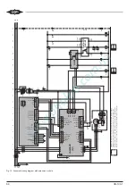
functioning. Based on the schematic wiring diagrams
(see chapter Operating modes, page 53) the STO func-
tion including the system integration can be checked
using the following procedure:
• Put the compressor into operation.
• Trigger the high-pressure switch (F5).
– The compressor must be switched off immediately
and the frequency inverter must send an STO
fault message.
• Close the high-pressure switch and/or the safety
chain.
– The STO fault is unlocked and the compressor is
restarted after a defined time delay.
6
Control functions
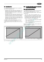
Graphical explanations of the control functions de-
scribed in the following sections, see figure 16, page
62.
Compressor start and STO
The compressor can only be started when it is released
(STO input closed), the start command is given (DI1
closed) and the start-to-start interval and the stop-to-
start interval (10 s) of the compressor has elapsed.
For a control by means of an external setpoint signal
and "0 .. Max" control characteristic, a setpoint > 1%
must also be active.
As soon as the start command is cancelled (DI1), the
compressor is shut down via the ramps.
If the release is cancelled (STO), however, it is directly
switched off.
"Ramps"
To optimize the operating performance, the compressor
ramps can be adjusted. For slow reacting systems such
as water chillers or refrigeration systems with only one
evaporator, we recommend selecting slower ramp
times while compound systems may require faster
ramps. Apart from the limitation of the external setpoint,
these ramps define the frequency change for the
"Force" function.
As standard, the shortest ramps are set for the respect-
ive compressors. To start and stop the compressor,
that means below the minimum frequency, the optimum
ramps are fixed in the VARIPACK frequency inverter
and therefore ensure a safe and reliable compressor
start.
"Start-to-start interval" (Time interval between two
compressor starts)
The compressor start activated by a VARIPACK fre-
quency inverter results in a lower mechanical stress on
the compressor drive gear and less heating of the mo-
tor compared to a direct start. By this, a higher number
of compressor starts per hour are allowed. An excess-
ive number of compressor starts, however, should be
avoided.
The "start-to-start interval" limits the maximum number
of compressor starts. If the defined time since the last
compressor start has not yet elapsed, the compressor
start is delayed. If the compressor is operated for a
longer period than the "start-to-start interval", it can be
restarted immediately after the stop. As standard, the
minimum "start-to-start interval" recommended for the
compressor is set. It can be extended to any desired
period in order to improve the operating performance of
the system and to increase the system efficiency by
avoiding very short cycles. If required, shorter time val-
ues than the preset and recommended ones can be
configured.
Relay "Compressor running" (DO2)
The relay "Compressor running" indicates the operating
condition of the compressor. It can be used, for ex-
ample, for switching off the oil heater or switching on
the additional fan or as a signal for the electronic ex-
pansion valve. As standard, the relay is switched on
after a successful compressor start after having
reached the minimum frequency and is switched off as
soon the frequency falls below the minimum value.
As an option, advanced or delayed switching of the re-
lay can be set. By setting a negative time interval, the
relay switches prior to the compressor start according
to the set interval. By setting a positive interval, the re-
lay switches after the compressor start, delayed by the
set time interval. An advanced relay can be used, for
example, to activate a start unloading, a delayed relay,
however, can be used to open the oil solenoid valve in
semi-hermetic screw compressors.
Содержание VARIPACK FDU+12
Страница 12: ...CB 100 1 12 1 2 3 4 Abb 7 Steuremodul abmontieren...
Страница 46: ...CB 100 1 46 1 2 3 4 Fig 7 Dismounting the control module...
Страница 64: ...CB 100 1 64 Fig 17 Graphical representation of the general control functions of the extension module...
Страница 70: ...Notes...
Страница 71: ...Notes...


