background image

CB-100-1

62

"Hold time after start at minimum frequency"

After the compressor start in temperature-controlled
systems with only one compressor there may be signi-
ficant pressure drops in the low-pressure circuit. The
reason for this is that, due to the high setpoint devi-
ation, the compressor is powered up too fast so that the
pressure cannot be regulated quickly enough by the ex-
pansion valve. This can be avoided by setting a time in-
terval after the start during which the minimum fre-
quency of the compressor is maintained before the
compressor switches to normal operation. As standard,
the value of 0 s is set.

Operation at 50 Hz (Force)

In case of long pipelines and rising lines or a not optim-
ally dimensioned suction gas line, there is a risk of oil
migration during the long partial load phases. If the fre-
quency and therefore the mass flow is increased, the
oil can be circulated back and a compressor shut off
can be avoided. This can be realized by the "Force"
function of the VARIPACK frequency inverter. If a lack
of oil in the oil tank or compressor is reported, the di-
gital input DI2 of the VARIPACK frequency inverter can
be activated to operate the compressor at least 50 Hz.

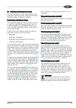
"Resonances avoidance"

If vibrations which cannot be eliminated easily occur in
a specific range of operating frequencies, these fre-
quencies can be avoided. For this, two frequency
ranges can be defined in which the compressor does
not remain during operation. When the setpoint ex-
ceeds the defined initial value, the frequency remains
constant until the setpoint has exceeded the end value
and the frequency range is skipped. When shutting
down, the frequency is maintained accordingly until the
setpoint has fallen below the initial value.

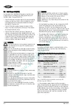
Automatic limitation of the maximum frequency

During operation in the field weakening mode, the
VARIPACK frequency inverter limits automatically the
operating frequency as soon as the maximum operat-
ing current of the compressor or the VARIPACK fre-
quency inverter is reached. This allows an economic di-
mensioning of the combination of compressor and
VARIPACK without running the risk that the VARIPACK
frequency inverter under exceptional operating condi-
tions (high condensing temperature, start-up or start
after a long standstill) switches to fault due to thermal
overload.

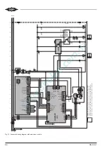
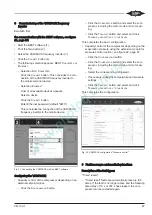
Fig. 16: Graphical representation of the general control functions

Содержание VARIPACK FDU+12

Страница 1: ...h 2 VARIPACK external BITZER Frequency Inverters FI Translation of the original Operating Instructions English 36 FDU 6 FDU 12 FEU 16 FEU 24 FGU 32 FGU 38 FHU 45 FHU 60 FHU 73 FJU 87 FJU 105 FJU 145 F...

Страница 2: ...egelung des Verdichters in Abh ngigkeit eines externen Sollwert Signals 19 5 4 2 Leistungsregelung des Verdichters in Abh ngigkeit des Verdampfungsdrucks mit dem Erweite rungsmodul zur Druckregelung O...

Страница 3: ...rheitsvorschriften und Nor men z B EN 378 EN 60204 1 die allgemein anerkannten Sicherheitsregeln die EU Richtlinien nationale Vorschriften 2 3 Sicherheitshinweise sind Anweisungen um Gef hrdungen zu v...

Страница 4: ...rt und spezielle externe Filter eingesetzt werden Betrieb an Generatoren Notstromaggregaten und Netzen mit Blindstromkompensationsanlagen nur nach R cksprache mit BITZER Erdschlussstrom 10 mA berspann...

Страница 5: ...ert 45 27 FEU 16 E 6 8 16 7 5 Inte griert 56 33 FEU 24 E 6 8 23 11 Inte griert 56 33 FGU 32 G 10 0 32 15 Inte griert 2x45 2x27 FGU 38 G 10 0 38 18 Inte griert 2x45 2x27 FHU 45 H 22 3 45 22 Inte griert...

Страница 6: ...er 1 Leistungsteil 2 K hlk rper 3 Obere Geh useabdeckung 4 Untere Geh useabdeckung 5 Steuermodul mit 5a Klemmleiste 5b Steckplatz f r SD Karte 6 Erweiterungsbausatz zur Druckregelung Option 7 Schnitts...

Страница 7: ...unzureichende oder blockierte Luftzirkulati on und Luftzufuhr an den Bel ftungsschlitzen und am K hlk rper des VARIPACK Frequen zumrichters kann zum Ausfall durch berhit zung f hren Mindestabst nde f...

Страница 8: ...b 3 Ma zeichnung FDU 6 FKU 260 bei Schaltschrankmontage Zeichnung zeigt FDU mit optionalem Bedienteil B mm B1 mm B2 mm B3 mm F mm H mm H1 mm H2 mm H3 mm L mm X mm FDU 6 FDU 12 100 80 10 M4 286 270 7 3...

Страница 9: ...ter erzeugten W rme au erhalb des Schalt schranks abgef hrt wird kann die Bel ftung des Schaltschranks auf ein Mini mum reduziert werden kann der VARIPACK Frequenzumrichter leichter sauber und trocken...

Страница 10: ...20 196 1 195 M5 FJU 87 FJU 145 260 218 5 227 292 312 26 208 220 M6 FKU 180 FKU 260 330 275 13 300 360 380 26 219 320 M8 H mm H1 mm H2 mm H3 mm H4 mm L mm L1 mm L2 mm X mm FEU 16 FEU 24 336 309 6 297 3...

Страница 11: ...iegelung l st sich Die Abdeckung nach vorne schieben und abneh men FEU 16 FKU 260 Bei diesen Typen muss das Steuermodul nicht ausge baut werden um die Geh useabdeckung abzunehmen siehe Abbildung 8 Sei...

Страница 12: ...CB 100 1 12 1 2 3 4 Abb 7 Steuremodul abmontieren...

Страница 13: ...montage Option Seite 9 Halterung von hinten unten an die beiden Befesti gungsl cher ansetzen und die mitgelieferten Schrau ben von vorne einsetzen und festziehen Untere Geh useabdeckung wieder aufstec...

Страница 14: ...lten sichern Mindestens 5 Minuten warten bis alle Konden satoren entladen sind Vor Wiedereinschalten FU Geh use verschlie en GEFAHR Sobald der VARIPACK Frequenzumrichter unter Spannung steht werden di...

Страница 15: ...uh 1 8 32 40 Class J FGU 38 33 5 40 50 Class J FHU 45 40 1 3 25 mm 2 2 0 M5 Ringkabel schuh 3 6 63 60 Class J FHU 60 54 7 80 80 Class J FHU 73 66 2 100 100 Class J FJU 87 78 8 M8 Stift f r Kabel schuh...

Страница 16: ...D vom Typ B verwenden die in der Lage sind auch Gleich fehlerstr me zu erfassen verwenden RCD in Bezug auf Systemkonfiguration und Umge bungsbedingungen bemessen 5 2 Leistungsanschl sse Stromkabel und...

Страница 17: ...hteranlauf Befehl X13 3 DI2 Force Betrieb des Verdichters mit einer Minimalfrequenz von 50 Hz X13 4 DI3 pe1 pe2 Externe Regelung ohne Funktion Mit Erweiterungsmodul Umschaltung von Ver dampfungstemper...

Страница 18: ...induktiven oder kapazitiven Lasten muss durch externe Ma nahmen erfolgen Max Strom 3 A ohmsche Last Information Die STO Eing nge m ssen beschaltet werden um den Anlauf des Verdichters zu erm glichen S...

Страница 19: ...ignal geregelt und ein zweiter Verdichter zugeschaltet werden 5 4 1 Leistungsregelung des Verdichters in Abh ngigkeit eines externen Sollwert Signals Steuercharakteristik Min Max Die VARIPACK Frequenz...

Страница 20: ...ertsignal von 1 0 1 V erfor derlich Das Sollwertsignal gibt die Frequenz zwi schen 0 Hz und der maximalen Frequenz vor Ist das Signal 1 aber niedriger als die minimale Fre quenz des Verdichters l uft...

Страница 21: ...um Vergleich eine einfache Sch tz schaltung wie sie blicherweise verwendet wird ohne die Verwendung von zwei Sch tzen in Reihe mit ge genseitiger berwachung entspricht einem max er reichbaren Sicherhe...

Страница 22: ...nal boxof the compressor R8 K10 15 Option X12 1 2 3 4 5 6 X13 Delta PII OLC K1 orange DI4 DI5 DO3 DI6 IMB DO3 FsC2 P24 V Output 0 V 0 V DI1 Start DI2 Force DI3 pe po1 2 P24 V Input 0 V Input VARIPACK...

Страница 23: ...atiometrischen Niederdruckmessum former Korrekte Funktion wird durch blaue LED ange zeigt X1 4 5 und 6 Eingang f r ratiometrischen Hochdruckmessum former Korrekte Funktion wird durch rote LED angezeig...

Страница 24: ...Input A 0 V Input B 0 V Status A Status B Analog I O REF Safety circuit STO U M1 V M2 W M3 Dig Inputs Output Dig Inputs Input PW Y 3 4 5 R7 Option M1 X14 2 1 DO2B DO2A DO1B DO1A RDY 2 1 VsC1 4 3 2 1 8...

Страница 25: ...Kabelhalterung des VARIPACK auflegen Das Motorkabel sollte andere Kabel nicht kreuzen Falls doch Kreuzungen nur im 90 Winkel vornehmen m glichst getrennt von der Zuleitung und den Steuerleitungen verl...

Страница 26: ...erdichter direkt abschalten GEFAHR Die STO Funktion stellt keine galvanische Tren nung dar und darf daher nicht f r Wartungs oder Reparaturarbeiten verwendet werden Sie ist nur eine elektronische Schu...

Страница 27: ...O Eing nge unabh ngig voneinander geschalten werden Je nach Einbindung in die Anlage kann das Sicherheitlevel der kompletten Anlage niedriger sein und muss vom An lagenbauer berechnet werden Die zur B...

Страница 28: ...aus Optional kann das Einschalten des Relais sowohl vor laufend als auch nachlaufend eingestellt werden Durch das Einstellen eines negativen Zeitintervalls schaltet das Relais entsprechend des eingest...

Страница 29: ...oge nannten Pump down Logik Der Digitaleingang zum An lauf des Verdichters DI1 muss dazu dauerhaft ge schlossen werden oder kann als Freigabe f r einen Steuerschalter eingesetzt werden Der Verdichter...

Страница 30: ...ten Druckwerts ab Gegen ber dem Verdampfungstemperatur Begrenzer Pump Down wird der Verdichter bei Erreichen dieses Grenzwerts sofort abgeschaltet und nicht ber die Rampe herunter gefahren Zudem wird...

Страница 31: ...Einschr nkungen kein firmware update m glich BEST Schnittstellenkonverter anschlie en BEST Schnittstellenkonverter mit dem RJ12 Kabel in die rechte Buchse XC3 an der Unterseite der Schnittstellenerwei...

Страница 32: ...ht des Bedienteils mit Befestigungsl chern und Aussparung auf der R ckseite f r externe Montage 7 2 1 Bausatz zur externen Montage des Bedienteils Der Bausatz zur externen Montage des optionalen Be di...

Страница 33: ...haltfl sche KONFIGURATION anklicken Parameter VERDICHTER anklicken und Verdichter inklusive Motorcode und Motorverschaltung aus w hlen Auf die Schaltfl sche BERTRAGEN klicken und BE NUTZEREINSTELLUNG...

Страница 34: ...0 s 9 berlast Permanentmagnetmotoren Timed reset 300 s 10 berstrom bei niedriger Drehzahl Timed reset 300 s 11 Umgebungs bertemperatur K hlk rper X Timed reset 300 s 12 Umgebungs bertemperatur Steuerm...

Страница 35: ...er des VARIPACK Frequenzumrichters hei Gefahr von Verbrennungen bei Ber hrung Vor Arbeiten am VARIPACK Frequenzumrich ter Stromversorgung trennen und mindestens 15 Minuten warten bis der K hlk rper ab...

Страница 36: ...5 4 Operating modes 53 5 4 1 Capacity control of the compressor depending on an external setpoint signal 53 5 4 2 Capacity control of the compressor depending on the evaporation pressure using the ex...

Страница 37: ...s 2 3 Safety references are instructions intended to prevent hazards Safety ref erences must be stringently observed NOTICE Instructions on preventing possible damage to equipment CAUTION Instructions...

Страница 38: ...wer factor correc tion units only after consultation with BITZER Earth fault current 10 mA Over voltage category III Enclosure class IP20 or Open Type UL and cUL Operating altitude and climatic condit...

Страница 39: ...45 27 FEU 16 E 6 8 16 7 5 Integ rated 56 33 FEU 24 E 6 8 23 11 Integ rated 56 33 FGU 32 G 10 0 32 15 Integ rated 2x45 2x27 FGU 38 G 10 0 38 18 Integ rated 2x45 2x27 FHU 45 H 22 3 45 22 Integ rated 2x8...

Страница 40: ...frequency inverter 1 Power stack 2 Heat sink 3 Upper housing cover 4 Lower housing cover 5 Control module with 5a Terminal strip 5b SD card slot 6 Extension kit for pressure control option 7 Interfac...

Страница 41: ...fficient or blocked air circulation and air sup ply at the ventilation slots and at the heat sink of the VARIPACK frequency inverter can lead to failure due to overheating Observe the minimum clearanc...

Страница 42: ...onal drawings FDU 6 FKU 260 for switch cabinet mounting drawing shows FDU with optional control panel B mm B1 mm B2 mm B3 mm F mm H mm H1 mm H2 mm H3 mm L mm X mm FDU 6 FDU 12 100 80 10 M4 286 270 7 3...

Страница 43: ...quency inverter is dissipated outside the switch cab inet the ventilation of the switch cabinet can be reduced to a minimum the VARIPACK frequency inverter can be kept clean and dry more easily 102 7...

Страница 44: ...127 M4 FHU 45 FHU 73 220 196 1 195 M5 FJU 87 FJU 145 260 218 5 227 292 312 26 208 220 M6 FKU 180 FKU 260 330 275 13 300 360 380 26 219 320 M8 H mm H1 mm H2 mm H3 mm H4 mm L mm L1 mm L2 mm X mm FEU 16...

Страница 45: ...der the upper hous ing cover A This will open the lock Slide the cover forwards and take it off FEU 16 FKU 260 With these types the control module does not need to be dismounted in order to take off t...

Страница 46: ...CB 100 1 46 1 2 3 4 Fig 7 Dismounting the control module...

Страница 47: ...over see chapter Through switch cabinet mounting option page 43 Place the fixture from behind at the bottom on the two fixing holes and insert the delivered screws from the front and tighten them Repl...

Страница 48: ...d secure it against being switched on again Wait for at least 5 minutes until all capacitors have been discharged Before switching on again close the FI housing DANGER As soon as the VARIPACK frequenc...

Страница 49: ...g 1 8 32 40 Class J FGU 38 33 5 40 50 Class J FHU 45 40 1 3 25 mm 2 2 0 M5 ring cable lug 3 6 63 60 Class J FHU 60 54 7 80 80 Class J FHU 73 66 2 100 100 Class J FJU 87 78 8 Pin M8 for cable lugs or w...

Страница 50: ...CD sensitive to all types of currents of type B that are capable of also detecting residual direct currents Select the RCD with respect to the system configura tion and environmental conditions 5 2 Po...

Страница 51: ...eve 0 25 0 75 mm Digital inputs Function X13 2 DI1 Start Compressor start command X13 3 DI2 Force Operation of the compressor at a minimum fre quency of 50 Hz X13 4 DI3 pe1 pe2 External control withou...

Страница 52: ...unning Technical data Potential free relay Max voltage 250 V AC or 30 V DC Protection from inductive or capacitive loads must take place by external measures Max current 3 A of resistive load Informat...

Страница 53: ...and a second compressor can be connec ted 5 4 1 Capacity control of the compressor depending on an external setpoint signal Min Max control characteristic The VARIPACK frequency inverters can be acti...

Страница 54: ...for starting the compressor The setpoint signal presets the frequency to a value between 0 Hz and the maximum frequency If the signal is 1 but lower than the minimum frequency of the compressor the c...

Страница 55: ...systems For comparison a simple contactor circuit that is usu ally used without using two contactors with mutual monitoring connected in series corresponds to a max reachable safety level of PLc SIL2...

Страница 56: ...oxof the compressor R8 K10 15 Option X12 1 2 3 4 5 6 X13 Delta PII OLC K1 orange DI4 DI5 DO3 DI6 IMB DO3 FsC2 P24 V Output 0 V 0 V DI1 Start DI2 Force DI3 pe po1 2 P24 V Input 0 V Input VARIPACK N1 X1...

Страница 57: ...ratiometric low pressure transmitter Correct function is indicated by blue LED X1 4 5 and 6 Input for ratiometric high pressure transmitter Correct function is indicated by red LED X2 1 Analogue outp...

Страница 58: ...N10 V Input A 0 V Input B 0 V Status A Status B Analog I O REF Safety circuit STO U M1 V M2 W M3 Dig Inputs Output Dig Inputs Input PW Y 3 4 5 R7 Option M1 X14 2 1 DO2B DO2A DO1B DO1A RDY 2 1 VsC1 4 3...

Страница 59: ...CK The motor cable should not cross other cables If they do crossov ers must be made at a triangle should be installed separately from the supply line and the control lines if possible If a parallel i...

Страница 60: ...e STO function As soon as the VARIPACK frequency inverter will detect an internal STO error it must be elim inated immediately NOTICE Defined switching points are no longer guaran teed if lines are to...

Страница 61: ...t for the respect ive compressors To start and stop the compressor that means below the minimum frequency the optimum ramps are fixed in the VARIPACK frequency inverter and therefore ensure a safe and...

Страница 62: ...l input DI2 of the VARIPACK frequency inverter can be activated to operate the compressor at least 50 Hz Resonances avoidance If vibrations which cannot be eliminated easily occur in a specific range...

Страница 63: ...rature ex ceeds the setpoint the rotation speed of the fans is in creased accordingly By adjusting the P band to the system inertia the quality of the control can be optim ized In addition a minimum f...

Страница 64: ...CB 100 1 64 Fig 17 Graphical representation of the general control functions of the extension module...

Страница 65: ...ce Restrictions no firmware update possible Connecting the BEST interface converter Plug the BEST interface converter into the right socket XC3 on the underside of the interface exten sion of the VARI...

Страница 66: ...h fixing holes and recess on the back for external mounting to the switch cabinet 7 2 1 Kit for external mounting of the control panel The kit for external mounting of the optional control panel part...

Страница 67: ...CONFIGURATION button Click the COMPRESSOR button and select the com pressor including the motor code and motor wir ing Click the TRANSMIT button and select and click TRANSMIT USER SETTINGS TO THE DEVI...

Страница 68: ...t Timed reset 300 s 7 Motor stall Timed reset 300 s 8 Inverse time Overload Timed reset 300 s 9 Motor I2T Overload permanent magnet motors Timed reset 300 s 10 Low speed I Overload at low frequency Ti...

Страница 69: ...the heat sink see chapter Replacing fans in the heat sink page 69 10 1 Replacing fans in the heat sink Prior to performing maintenance work on the VARIPACK frequency inverter CAUTION In operation the...

Страница 70: ...Notes...

Страница 71: ...Notes...

Страница 72: ...au GmbH Eschenbr nnlestra e 15 71065 Sindelfingen Germany Tel 49 0 70 31 932 0 Fax 49 0 70 31 932 147 bitzer bitzer de www bitzer de Subject to change nderungen vorbehalten Toutes modifications r serv...

Отзывы: