1
P A R T S L I S T
Item
Qty
Description
Item
Qty
Description
A
1
Back Plate
H
1
Return Spring
B
4
5/16” X 2 1/2” Fully Threaded Hex Bolt
I
1
Spring Washer
C
8
5/16” Flat Washer
J
1
3/8” Hex Lock Nut
D
4
5/16” Flange Nut
K
1
Cover Plate
E
1
Rim Assembly
L
2
1/4” Self Tapping Screw
F
1
1/2” Pivot Bolt
M
1
Net
G
1
1/2” Lock Nut
♦
Inspect all contents prior to installation. Report any missing parts to dealer immediately.
♦
Read all instructions before proceeding.
—— Instruction Manual ——
F
AST
B
REAK
Flex Goal
Date: 3/9/05 Rev: 2 B.A. N.J.C. File: Drive.f\publisher\29jrinst Ref#: 910081
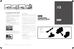
1. Mount
back plate
(A) to backboard/extension arm with
5/16 X 2 1/2” fully threaded hex bolts
(B),
5/16”
flat washers
(C) and
5/16” flange nuts
(D). Level backboard and
back plate
(A) prior to tightening
hardware.
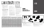
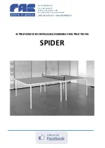
2. Install
rim assembly
(E) to the
back plate
(A) by feeding the return eye bolt through the clearance hole
shown in figure 1. The
back plate
(A) and
rim assembly
(E) are designed to fit tightly together, you may
need to use a soft face hammer to encourage this assembly.
3. Align the pivot bolt holes and install 1/2”
pivot bolt
(F) through entire assembly, use 1/2”
lock nut
(G) to
secure pivot bolt.
IT IS VERY IMPORTANT THAT THE PAINTED SIDE OF THE LOCK NUT (G)
IS PLACED (STARTED) ON THE PIVOT BOLT (F) FIRST TO PROPERLY LOCK PIVOT
BOLT.
Take care not to damage the threads. You may need to tap the 1/2”
pivot bolt
(F) through the
assembly with a hammer. Tighten bolt and nut, if your assembly does not flex freely loosen
1/2” lock nut
(G)1/2 turn. See Figure 1.
4. Push the front of
rim assembly
(E) up to seat the assembly in home position, this will facilitate installing
return spring
(H),
spring washer
(I) and
3/8” lock nut
(J). Using a 9/16” wrench tighten the
3/8” lock nut
(J) until 2-3 threads are showing below the nut. Spring tension can be adjusted to player preference. See
Figure 1.
5. Install
cover plate
(K) with
1/4” self tapping screws
(L).
6. Install
net
(M).