background image

Termaline® Semiconductor Load Resistor

12

Specifications

Replacement Parts

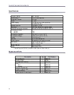
Frequency Range

DC – 28 MHz

Power Rating

1000 W continuous duty

Impedance, Nominal

50 ohms

VSWR

1.1 max

VSWR Stability

< 0.1 dB, from 0 to 100% rated power 
at stability frequency

Stability Frequency

13.56 MHz ± 10 kHz

Connector

“QC” Type, Female LC normally supplied

Interlock Thermoswitch (Optional)

Normally closed. Opens at 236 °C (457 °F)

Thermoswitch Rating 

115 VAC 
230 VAC

 
10 A 
 5 A

Temperature, Operating

+5 to +40 °C (+41 to +104 °F)

Temperature, Storage

– 40 to +45 °C (–


40 to +113 °F)

Altitude

*

* Derate RF power by 250 W for every 305m (1,000 ft.) above 1,520m (5,000 ft.)

1520 m (5000 ft.)

Humidity

95% noncondensing max

Cooling method

Oil dielectric and convection currents

Dimensions

17.5" L x 7.5" W x 13

1

8

" H 

(445 x 190 x 334 mm)

Weight, Nominal

27.8 lb. (12.6 kg)

Finish

Black Epoxy Resin

Description

Qty

Part Number

RF Load Resistor

1

8890-060

Resistor O-Ring

1

5-230

Clamping Band Assembly

1

2430-055

Plug 

Vent 
Shipping

1

 
2450-094 
2450-049

Overtemp Thermoswitch

1

8890-008

Coolant, 1.5 gal (5.7 liter)

1

5-1070-3

Radiator Assembly

1

8860-002-2

Access Plug 3/4"-14 Hex Socket

1

5020-103

Содержание Termaline 8860SC Series

Страница 1: ...tor Load Resistor Series 8860SC Operation Manual Copyright 2016 by Bird Technologies Inc Instruction Book Part Number 920 8860 SEMICON Rev B Termaline and Tenuline are Registered Trademarks of Bird El...

Страница 2: ...to remove the RF transmission line while RF power is present WARNING Do Not Service Or Adjust Alone Under no circumstances should any person reach into an enclosure for the purpose of service or adjus...

Страница 3: ...ck hazard exists if the precautions in the instruction manual are not followed The caution symbol appears on the equipment indicating there is important information in the instruction manual regarding...

Страница 4: ...On page 4 On page 5 On page 10 CAUTION This load is designed for operation in a horizontal position only with the vent plug up Do not use in any other manner CAUTION Do not contaminate the coolant wit...

Страница 5: ...GURIDAD DEL INSTRUMENTO BENUTZUNG WIRD DAS GER T AUF ANDERE WEISE VERWENDET ALS VOM HERSTELLER BESCHRIEBEN KANN DIE GER TESICHERHEIT BEEINTR CHTIGT WERDEN UTILISATION TOUTE UTILISATION DE CET INSTRUME...

Страница 6: ...ARTUNG DES GER TES GELTEN NUR F R GESCHULTES FACHPERSONAL ZUR VERMEIDUNG GEF HRLICHE ELEKTRISCHE SCHOCKS SIND WARTUNGSARBEITEN AUSSCHLIE LICH VON QUALIFIZIERTEM SERVICEPERSONAL DURCHZUF HREN ENTRENTIE...

Страница 7: ...RATING BRANCHER LE VERROUILLAGE L METTEUR AVANT EMPLOI CONECTE EL INTERBLOQUEO AL TRANSMISOR ANTES DE LA OPERACION VOR INBETRIEBNAHME VERRIEGELUNG AM SENDER ANSCHLIESSEN PRIMA DI METTERE IN FUNZIONE L...

Страница 8: ...Termaline Semiconductor RF Load Resistor lists equipment supplied and optional equipment and provides power up instructions Theory of Operation Describes how to connect Semiconductor RF Load Resistor...

Страница 9: ...Setting Up 3 Mounting the Load Resistor 3 Installing the Thermoswitch 4 Installing the Interlock Connection 5 Connecting the RF Power 6 Chapter 4 Operating Instructions 7 Normal Operation 7 Operation...

Страница 10: ...Termaline Semiconductor Load Resistor ix Specifications 12 Replacement Parts 12 Available QC Type Connectors 13 Limited Warranty 14...

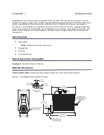
Страница 11: ...ar fins form mounting flanges which can be used as supports for freestanding use or as brackets for fixed mounting A vent plug at the top of the unit relieves internal pressure from coolant expansion...

Страница 12: ...rmal characteristics carries heat from the resistor to the walls of the cooling tank where radiator fins surrounding the tank transfer the heat to the air When the coolant is heated thermal expansion...

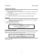
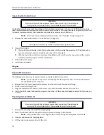
Страница 13: ...g from the load 2 Replace the shipping plug with the vent plug Note Refer to Figure 1 for images of the plugs Mounting the Load Resistor Place the load in a dry dust and vibration free environment Do...

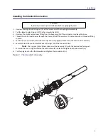
Страница 14: ...position there is no danger of the coolant pouring out through the socket plug hole 3 Remove the socket plug just above the connector assembly using a 9 16 hex wrench 4 Replace the plug with the ther...

Страница 15: ...with its threaded fitting in place 5 Service the control switch wire with short tips and put spaghetti sleeves over the wire ends if necessary 6 Securely solder the control switch leads to the lugs G...

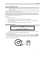
Страница 16: ...QC Connector Coupling Use 50 ohm coaxial cable such as RG 218 U or 220 U 17A or 19A appropriate for the frequency and power level of operation Use a cable connector which will mate with the one on th...

Страница 17: ...rt periods If this is likely make sure the interlock is properly connected to prevent damage to the load Shutdown These loads are passive devices so have no way of being turned off Turn off RF power a...

Страница 18: ...e RF power is being applied Leaking RF energy is a potential health hazard WARNING Disconnect the unit from all power sources before servicing The unit may be energized from multiple sources The poten...

Страница 19: ...hms or use a resistance bridge Use low resistance leads preferably a short piece of 50 ohm coaxial cable fitted with an appropriate connector or alligator clips Temperature of the load should be stabi...

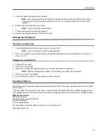
Страница 20: ...Bird QC connectors Note If not using the LC connector normally supplied the frequency and power must be limited to the capabilities of the connector 1 Remove four 8 32 round head machine screws from t...

Страница 21: ...40 to 113 F Shipping the Load Resistor 1 Remove the vent plug 2 Install the shipping plug 3 Wrap the vent plug with padding and tape it to the side of the load for protection Note With the shipping p...

Страница 22: ...erating 5 to 40 C 41 to 104 F Temperature Storage 40 to 45 C 40 to 113 F Altitude Derate RF power by 250 W for every 305m 1 000 ft above 1 520m 5 000 ft 1520 m 5000 ft Humidity 95 noncondensing max Co...

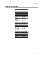
Страница 23: ...LC Male 4240 025 Open Term 10 32 Nut 4240 080 LT Female 4240 018 LT Male 4240 012 N Female 4240 062 N Male 4240 063 SC Female 4240 090 SMA Female 4240 336 SMA Male 4240 334 7 16 Jack IEC Type 169 4 4...

Страница 24: ...ry such claim for breach of these warranties shall be deemed to be waived by Buyer unless made in writ ing within ten days from the date of discovery of the defect The above warranties shall not exten...

Отзывы: