background image

6

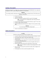
Installing Thermoswitch 

Bird 8860 series loads can be equipped with an optional interlock thermoswitch, P/N 8890-008. It is normally closed, 
opening at 236 °C (457 °F), with a rating of 10A @ 120Vac and 5A @ 230Vac.

1.

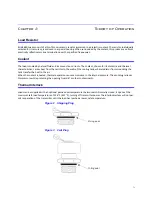
Remove the vent plug. 

2.

Install the shipping plug.

3.

Stand the unit on its front, supporting it so that the connector is not damaged. 

Note:

In this position there is no danger of the coolant pouring out through 

the socket plug hole.

4.

Remove the socket plug just above the connector assembly, using a 

9

16

" hex wrench.

5.

Replace the plug with the thermoswitch. 

6.

Apply pipe sealing compound to the external threads of the thermoswitch sparingly, 
ONLY. 

1.

Check for coolant leaks upon completion.

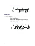
Interlock Connection

1.

Unscrew the large knurled ring-nut (A) at the lower end of the coupling jack assembly. 

2.

Pull the large knurled ring-nut off the thermoswitch jack (B). 

3.

Unscrew the small knurled cover fitting from the base plug (D) of the connector to 
release the base.

4.

Thread the control switch wires through the clamp (E) with the washers (F) inside 
and with its threaded fitting in place. 

5.

Service the control switch wire with short tips and put spaghetti sleeves over the 
wire ends if necessary.

6.

Securely solder the control switch leads to the lugs (G) of the connector base.

Note:

The ring-nut (A) must be in place over the base plug (D) with the knurled 

end facing out.

7.

Screw on the cover ring, then fasten the cable clamp (E) in place and tighten both 
yoke screws (H).

2.

Put the plug back on the thermoswitch and tighten the nut (A).

WARNING

The vent plug must be used at all times when the unit is operating or cooling. Failure to do so could result in an 

explosion or severe burns.

CAUTION

Do not contaminate the coolant with pipe sealant.

CAUTION

If installed, connect optional interlock before applying RF power.

Содержание TERMALINE 8860 Series

Страница 1: ...OAD RESISTOR SERIES 8860 COVERING MODELS Copyright 2012 by Bird Electronic Corporation Instruction Book Part Number 920 8860S Rev D Termaline and Tenuline are Registered Trademarks of Bird Electronic...

Страница 2: ...I am not blank...

Страница 3: ...umstances should any person reach into an enclosure for the purpose of service or adjustment of equipment except in the presence of someone who is capable of rendering aid WARNING Safety Earth Ground...

Страница 4: ...formation in the instruction manual regarding that particular area This symbol indicates that the unit radiates heat and should not be touched while hot WARNING The vent plug must be used at all times...

Страница 5: ...6 See pages 13 CAUTION This load is designed for operation in a horizontal position only with the vent plug up Do not use in any other manner CAUTION Do not contaminate the coolant with pipe sealant...

Страница 6: ...EL INSTRUMENTO BENUTZUNG WIRD DAS GER T AUF ANDERE WEISE VERWENDET ALS VOM HERSTELLER BESCHRIEBEN KANN DIE GER TESICHERHEIT BEEINTR CHTIGT WERDEN UTILISATION TOUTE UTILISATION DE CET INSTRUMENT QUI N...

Страница 7: ...GELTEN NUR F R GESCHULTES FACHPERSONAL ZUR VERMEIDUNG GEF HRLICHE ELEKTRISCHE SCHOCKS SIND WARTUNGSARBEITEN AUSSCHLIE LICH VON QUALIFIZIERTEM SERVICEPERSONAL DURCHZUF HREN ENTRENTIEN L EMPLOI DES INST...

Страница 8: ...ANCHER LE VERROUILLAGE L METTEUR AVANT EMPLOI CONECTE EL INTERBLOQUEO AL TRANSMISOR ANTES DE LA OPERACION VOR INBETRIEBNAHME VERRIEGELUNG AM SENDER ANSCHLIESSEN PRIMA DI METTERE IN FUNZIONE L APPARECC...

Страница 9: ...e title page Chapter Layout Introduction Describes the features of the Bird Termaline Semiconductor RF Load Resistor lists equipment supplied and optional equipment and provides power up instructions...

Страница 10: ...oswitch 6 Interlock Connection 6 Connecting RF Power 7 QC Connector Coupling 7 13 30 Coupling 7 Swivel Flanged Coupling 7 Unflanged Coupling 8 Chapter 4 Operating Instructions 9 Normal Operation 9 Ope...

Страница 11: ...ts for fixed mounting A vent plug at the top of the unit relieves internal pressure from coolant expansion The load s simple and rugged design minimizes maintenance requirements Items Supplied Load Re...

Страница 12: ...2...

Страница 13: ...eat from the resistor to the walls of the cooling tank where radiator fins surrounding the tank transfer the heat to the air When the coolant is heated thermal expansion causes an increase in the inte...

Страница 14: ...4...

Страница 15: ...ce Refer to DC Resistance on page 12 for details 1 Remove the shipping plug from the load 2 Replace the shipping plug with the vent plug Refer to Figure 1 and Figure 2 for pic tures of the plugs Mount...

Страница 16: ...2 Pull the large knurled ring nut off the thermoswitch jack B 3 Unscrew the small knurled cover fitting from the base plug D of the connector to release the base 4 Thread the control switch wires thr...

Страница 17: ...uple the swivel flange with a flanged RF transmission line use an appropriate coupling kit Refer to Figure 5 1 Insert the center bullet 2 Push it in until it is fully seated 3 Connect the coaxial inpu...

Страница 18: ...the center bullet 2 Bottom it on the midpoint nibs 3 Position the outer sleeve with clamping bands over the input connector 4 Set the transmission line snugly against the coupling stops 5 Position th...

Страница 19: ...ort periods If this is likely make sure the interlock is prop erly connected to prevent damage to the load Shutdown These loads are passive devices so have no way of being turned off Turn off RF power...

Страница 20: ...10...

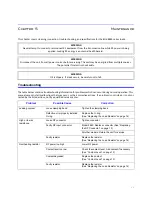
Страница 21: ...multiple sources The potential for electric shock exists WARNING Oil is slippery If a leak occurs be careful not to fall Problem Possible Cause Correction Leaking coolant Loose clamping band Tighten...

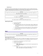
Страница 22: ...start before the load is put into service and should be measured annually Perform the following steps and record the value for future comparison Make sure that you have an ohmmeter with an accuracy o...

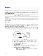
Страница 23: ...ird QC connector which allows easy changing of the RF connector This does not disturb the coolant seal or affect the electrical continuity of the load To change the connector proceed as fol lows 1 Rem...

Страница 24: ...ntire load resistor assembly Note It cannot be further disassembled 7 Put the clamping band in place and tighten it 3 Remove the shipping plug and install the vent plug Storage and Shipment Storing th...

Страница 25: ...reason request an RMA through the Bird Technologies website link shown below All instruments returned must be shipped prepaid and to the attention of the RMA number Bird Service Center 30303 Aurora R...

Страница 26: ...8863 8864 8864D Female LC 1 5 8 unflanged 1 5 8 EIA flanged Female 13 30 3 1 8 unflanged 3 1 8 EIA flanged Interlock Thermoswitch Normally closed Opens at 236 C 457 F Thermoswitch Rating 115 Vac 230 V...

Страница 27: ...8864D 1 8890A050 8895 015 8892 015 8862 017 8897 003 8891 050 8891 071 Resistor O Ring 1 5 230 Clamping Band Assembly 1 2430 055 Plug Vent Shipping 1 2450 094 2450 049 Overtemp Thermoswitch 1 8890 008...

Страница 28: ...LC Male 4240 025 Open Term 10 32 Nut 4240 080 LT Female 4240 018 LT Male 4240 012 N Female 4240 062 N Male 4240 063 SC Female 4240 090 SMA Female 4240 336 SMA Male 4240 334 7 16 Jack IEC Type 169 4 4...

Страница 29: ...such claim for breach of these warranties shall be deemed to be waived by Buyer unless made in writing within ten 10 days from the date of discovery of the defect The above warranties shall not extend...

Страница 30: ...20...
Отзывы: