background image

Hi-Fi Z97Z7 

CHAPTER 1: INTRODUCTION 

1.1  Before You Start 

Thank you for choosing our product. Before you start installing the 
motherboard, please make sure you follow the instructions below: 

  Prepare a dry and stable working environment with sufficient 

lighting. 

  Always disconnect the computer from power outlet before 

operation. 

  Before you take the motherboard out from anti-static bag, 

ground yourself properly by touching any safely grounded 
appliance, or use grounded wrist strap to remove the static 
charge. 

  Avoid touching the components on motherboard or the rear 

side of the board unless necessary. Hold the board on the 
edge, do not try to bend or flex the board. 

  Do not leave any unfastened small parts inside the case after 

installation. Loose parts will cause short circuits which may 
damage the equipment. 

  Keep the computer from dangerous area, such as heat 

source, humid air and water. 

  The operating temperatures of the computer should be 0 to 

45 degrees Celsius. 

  To avoid injury, be careful of: 

Sharp pins on headers and connectors 
Rough edges and sharp corners on the chassis 
Damage to wires that could cause a short circuit 

1.2 Package 

Checklist 

  Serial ATA Cable x4 

  Rear I/O Panel for ATX Case x1 

  User’s Manual x1 

  Fully Setup Driver DVD x1 

Note:

 The package contents may be different due to the sales region or models in which it was 

sold. For more information about the standard package in your region, please contact your dealer 
or sales representative. 


Содержание Hi-Fi Z97Z7

Страница 1: ...ht to revise this publication and to make changes to the contents here without obligation to notify any party beforehand Duplication of this publication in part or in whole is not allowed without first obtaining the vendor s approval in writing The content of this user s manual is subject to be changed without notice and we will not be responsible for any mistakes found in this user s manual All t...

Страница 2: ...nstall System Memory 9 2 5 Expansion Slots 10 2 6 Jumper Setting 12 2 7 Headers Connectors 13 2 8 Smart Switches Indicators 18 Chapter 3 UEFI BIOS Software 19 3 1 UEFI BIOS Setup 19 3 2 BIOS Update 19 3 3 Software 23 Chapter 4 Useful Help 33 4 1 Driver Installation 34 4 2 AMI BIOS Beep Code 35 4 3 AMI BIOS Post Code 35 4 4 Troubleshooting 37 4 5 RAID Functions 38 Appendix Specifications in Other L...

Страница 3: ...do not try to bend or flex the board Do not leave any unfastened small parts inside the case after installation Loose parts will cause short circuits which may damage the equipment Keep the computer from dangerous area such as heat source humid air and water The operating temperatures of the computer should be 0 to 45 degrees Celsius To avoid injury be careful of Sharp pins on headers and connecto...

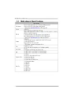
Страница 4: ...mory support list Storage INTEL Z97 1x SATA Express Connector compatible with 2x SATA 6 0 Gb s ports 4x SATA 6Gb s Connector Supports RAID 0 1 10 5 AHCI SRT SATA Express Connector is shared with M 2 slot LAN Realtek RTL 8111GR 10 100 1000 Mb s auto negotiation Half Full duplex capability Audio Codec ALC892 7 1 Channels High Definition Audio Biostar Hi Fi USB 6x USB 3 0 port 4 on rear I Os and 2 vi...

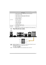
Страница 5: ... Front Audio Header 1x Clear CMOS Header 1x Consumer IR Header 1x Serial Port Header 1x TPM Header supports TPM 1 2 Form Factor ATX Form Factor 305 mm x 244 mm OS Support Windows 7 8 8 1 Biostar reserves the right to add or remove support for any OS with or without notice 1 4 Rear Panel Connectors Note1 HDMI DVI D VGA ports only work with an Intel integrated Graphics Processor Note2 Maximum resolu...

Страница 6: ...Motherboard Manual 4 1 5 Motherboard Layout Note represents the 1 st pin ...

Страница 7: ...n and make good preservation for future use When the CPU is removed cover the Pin Cap on the empty socket to ensure pin legs won t be damaged Note2 The motherboard might equip with two different types of pin cap Please refer below instruction to remove the pin cap Step 2 Pull the socket locking lever out from the socket and then raise the lever up Step 3 Remove the Pin Cap ...

Страница 8: ...ing or sliding the processor in the socket Note1 The LGA1155 CPU is not compatible with LGA 1150 socket Do not install a LGA 1155 CPU on the LGA 1150 socket Note2 The CPU fits only in one correct orientation Do not force the CPU into the socket to prevent damaging the CPU Step 5 Hold the CPU down firmly and then lower the lever to locked position to complete the installation ...

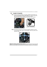
Страница 9: ...est to the CPU fan connector Ensure the fastener slots are pointing perpendicular to the heatsink Step 2 Press down two fasteners at one time in a diagonal sequence to secure the CPU fan assembly in place As each fastener locks into position a click should be heard Note1 Do not forget to connect the CPU fan connector Note2 For proper installation please kindly refer to the installation manual of y...

Страница 10: ...1 Ground 2 12V 3 FAN RPM rate sense 4 Smart Fan Control By Fan SYS_FAN1 2 3 System Fan Header Pin Assignment 1 Ground 2 12V 3 FAN RPM rate sense 4 Smart Fan Control By Fan Note CPU_FAN1 2 SYS_FAN1 2 3 support 4 pin and 3 pin head connectors When connecting with wires onto connectors please note that the red wire is the positive and should be connected to pin 2 and the black wire is Ground and shou...

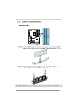
Страница 11: ...d Align a DIMM on the slot such that the notch on the DIMM matches the break on the slot Step 2 Insert the DIMM vertically and firmly into the slot until the retaining clips snap back in place and the DIMM is properly seated Note If the DIMM does not go in smoothly do not force it Pull it all the way out and try again ...

Страница 12: ...s memory not installed Note The DRAM bus width of the memory module must be the same x8 or x16 2 5 Expansion Slots Install an Expansion Card You can install your expansion card by following steps 1 Read the related expansion card s instruction document before install the expansion card into the computer 2 Remove your computer s chassis cover screws and slot bracket from the computer 3 Place a card...

Страница 13: ...nterconnect Slots The PCI slots support cards used in PCs include LAN cards sound cards modems TV tuner cards and other cards that comply PCI standard PCIE M2 M 2 Key M Socket 3 Slot M 2 formerly known as NGFF is a small form factor card and supports ultimate performance SSD or cache The M 2 slot supports M 2 SATA3 6 0 Gb s module and M 2 PCI Express module up to Gen2 x2 10 Gb s The M 2 slot suppo...

Страница 14: ...safe setting and the CMOS data Please carefully follow the procedures to avoid damaging the motherboard 3 1 Pin 1 2 Close Normal Operation default 3 1 Pin 2 3 Close Clear CMOS data Clear CMOS Procedures 1 Remove AC power line 2 Set the jumper to Pin 2 3 close 3 Wait for five seconds 4 Set the jumper to Pin 1 2 close 5 Power on the AC 6 Load Optimal Defaults and save settings in CMOS JLN2 LN2 Mode ...

Страница 15: ...V 22 5V 10 12V 23 5V 11 12V 24 Ground 12 3 3V ATXPWR2 ATX Power Source Connector The connector provides 12V to the CPU power circuit If the CPU power plug is 4 pin please plug it into Pin 1 2 5 6 of ATXPWR2 Pin Assignment 1 12V 2 12V 3 12V 4 12V 5 Ground 6 Ground 7 Ground 8 Ground Note1 Before you power on the system please make sure that both ATXPWR1 and ATXPWR2 connectors have been plugged in No...

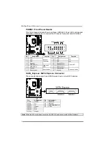
Страница 16: ...eaker 12 Power LED Power LED 5 HDD LED Hard drive LED 13 Power LED 6 HDD LED 14 Power LED 7 Ground Reset button 15 Power button Power on button 8 Reset control 16 Ground SATA_Express SATA Express Connector The connector can support one SATA Express device or two SATA devices Pin Assignment Pin Assignment S1 S8 Ground P1 Reserved S2 S9 TX P2 PERST S3 S10 TX P3 CLKREQ DEVSLP S4 S11 Ground P4 IFDet S...

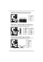
Страница 17: ...can be connected with a wide range of external peripherals Pin Assignment Pin Assignment 1 VBUS0 11 D2 2 SSRX1 12 D2 3 SSRX1 13 Ground 4 Ground 14 SSTX2 5 SSTX1 15 SSTX2 6 SSTX1 16 Ground 7 Ground 17 SSRX2 8 D1 18 SSRX2 9 D1 19 VBUS1 10 ID 20 Key F_USB1 2 Header for USB 2 0 Ports at Front Panel This header allows user to add additional USB ports on the PC front panel and also can be connected with...

Страница 18: ...nect a high definition front panel audio module to this connector to avail of the motherboard s high definition audio capability Note2 Please try to disable the Front Panel Jack Detection if you want to use an AC 97 front audio output cable The function can be found via O S Audio Utility JSPDIFOUT1 Digital Audio out Connector The connector is for connecting the S PDIF output bracket Pin Assignment...

Страница 19: ...rDA serial output 6 IR Power TPM Trusted Platform Module Header TPM1 2 This header allows you to store cryptographic keys that protect information Pin Assignment Pin Assignment 1 CLK_PCI_TPM 2 Ground 3 LFRAME 4 Key 5 PL_RST2 6 VCC5 7 FWH3 8 FWH2 9 VCC3_3 10 FWH1 11 FWH0 12 Ground 13 SMBCLK 14 SMBDATA 15 AUX33 16 SERIRQ 17 Ground 18 CLK_RUN 19 SUS_STAT 20 LDRQJ1 ...

Страница 20: ...on board Power Switch button SW_RST1 This is an on board Reset button BIOS POST Code CPU Temperature Indicator This indicator will show POST code while booting After the booting sequence it will show current CPU temperature in Celsius Please refer to Chapter 4 3 for all the BIOS POST codes ...

Страница 21: ...ity It enables automated updating while in the Windows environment Using this utility the BIOS can be updated from a file on a hard disk a USB drive a flash drive or a USB hard drive or a CD ROM or from the file location on the Web BIOSTAR BIOS Flasher Note1 This utility only allows storage device with FAT32 16 format and single partition Note2 Shutting down or resetting the system while updating ...

Страница 22: ...shows up press DEL key to enter BIOS setup After entering the BIOS setup please go to the Save Exit using the Restore Defaults function to load Optimized Defaults and select Save Changes and Reset to restart the computer Then the BIOS Update is completed BIOS Update Utility through the Internet 1 Installing BIOS Update Utility from the DVD Driver 2 Please make sure the system is connected to the i...

Страница 23: ...ll be asked you to reboot the system Click OK to reboot 8 While the system boots up and the full screen logo shows up press DEL key to enter BIOS setup After entering the BIOS setup please go to the Save Exit using the Restore Defaults function to load Optimized Defaults and select Save Changes and Reset to restart the computer Then the BIOS Update is completed BIOS Update Utility through a BIOS f...

Страница 24: ...e process is finished click on OK to reboot the system 7 While the system boots up and the full screen logo shows up press DEL key to enter BIOS setup After entering the BIOS setup please go to the Save Exit using the Restore Defaults function to load Optimized Defaults and select Save Changes and Reset to restart the computer Then the BIOS Update is completed Backup BIOS Click the Backup BIOS but...

Страница 25: ...te2 The information and pictures described below are for your reference only The actual information and settings on board may be slightly different from this manual TOverclocker TOverclocker presents a simple Windows based system performance enhancement and manageability utility It features several powerful and easy to use tools such as Overclocking for enhancing system performance also for specia...

Страница 26: ...ove overclock setting ideally the difference will be based on the selected CPU model Note2 Overclock is an optional process but not a must do process it is not recommended for inexperienced users Therefore we will not be responsible for any hardware damage which may be caused by overclocking We also would not guarantee any overclocking performance Note3 Press TOVERCLOCKER logo it will display info...

Страница 27: ...ose BMP as your boot logo so as to customize your computer Please follow the step by step instructions below to update boot logo Load Image Choose the picture as the boot logo Transform Transform the picture for BIOS and preview the result Update Bios Write the picture to BIOS Memory to complete the update ...

Страница 28: ... that you would like to send the copy to Provide the name of the power supply manufacturer and the model no Send the mail out Save these information to a txt file Exit this dialog Select your area or the area close to you Provide the name of the memory module manufacturer Describe condition of your system represents important information that you must provide Without this information you may not b...

Страница 29: ...l Note1 We will not share customer s data with any other third parties so please feel free to provide your system information while using eHot Line service Note2 If you are not using Outlook Express as your default e mail client application you may need to save the system information to a txt file and send the file to our tech support with other e mail application Go to the following website http ...

Страница 30: ... you want to use an AC 97 front audio output cable please disable the Front Panel Jack Detection setting This setting can be found via O S Audio Utility Smart EAR Utility High Low Gain Switch Keep the gain switch to low for low impedance headphone and set to high for high impedance headphone Mute Button To disable system sound Volume Control Knob The volume can be finely adjusted by turning the kn...

Страница 31: ...2 Click on start menu and input regedit in the search bar Press enter to open the registry editor Look for the following directory in the registry editor Computer HKEY_LOCAL_MACHINE SOFTWARE Intel Intel Smart Connect Technology Right click on Intel Smart Connect Technology and select New Key Type OEM Note Intel Smart Connect Technology is for S3 mode only During the updating process the monitor wi...

Страница 32: ... History along with other settings To launch the application select the application Intel Smart Connect Technology in the Start menu Windows 7 or Start screen Windows 8 8 1 to launch the configuration GUI Once launched the following is presented Note For detailed setting of Intel Smart Connect Technology please check the below link http www intel com support services smartconnect sb CS 033109 htm ...

Страница 33: ...p www intel com p en_US support Installing Intel RST Step 1 BIOS Setting 1 1 Go to Advanced Menu ACPI Settings and set ACPI Sleep State to S3 Suspend to RAM 1 2 Go to Advanced Menu SATA Configuration and set SATA Mode Selection to AHCI 1 3 Go to Advanced Menu and set Intel R Rapid Start Technology to Enabled 1 4 Save your changes and then exit the BIOS Setup Step 2 Operating System Installation St...

Страница 34: ...rt Technology automatically We recommend you restart the system after this installation is complete Step 4 Configuring Intel Rapid Start Application Launch the Intel Rapid Start Technology Manager application from Start All Programs Intel or click the icon in the notification area ...

Страница 35: ...set Time Consumption Auto Phase Mode Maxi Energy Mode Typical Mode Medium Mode Performance Mode G P U Mode Setting This utility provides five modes upon your requirements to improve system performance or to save power consumption Note Even if the modes saving more power consumption are chosen the system still can keep excellent performance Auto Phase Mode System switches the mode automatically acc...

Страница 36: ...m Click on each device driver to launch the installation program B Software Installation To install the software please click on the Software icon The setup guide will list the software available for your system click on each software title to launch the installation program C Manual Aside from the paperback manual we also provide manual in the Driver DVD Click on the Manual icon to browse for ava...

Страница 37: ...CPU post memory initialization Application Processor s AP initialization 35 CPU post memory initialization Boot Strap Processor BSP selection 36 CPU post memory initialization System Management Mode SMM initialization 37 Post Memory North Bridge initialization is started 3B Post Memory North Bridge initialization North Bridge module specific 4F DXE IPL is started 60 DXE Core is started F0 Recovery...

Страница 38: ...ect 99 Super IO Initialization 9A USB initialization is started 9B USB Reset 9C USB Detect 9D USB Enable A0 IDE initialization is started A1 IDE Reset A2 IDE Detect A3 IDE Enable A4 SCSI initialization is started A5 SCSI Reset A6 SCSI Detect A7 SCSI Enable A8 Setup Verifying Password A9 Start of Setup AB Setup Input Wait AD Ready To Boot event AE Legacy Boot event AF Exit Boot Services event B0 Ru...

Страница 39: ...d applications files 2 Reformat the hard drive Re install applications and data using backup disks Screen message shows Invalid Configuration or CMOS Failure Review system s equipment Make sure correct information is in setup System cannot boot after user installs a second hard drive 1 Set master slave jumpers correctly 2 Run SETUP program and select correct drive types Call the drive manufacturer...

Страница 40: ... parity Drawbacks Does not deliver any fault tolerance If any drive in the array fails all data is lost Fault Tolerance No Total Capacity Minimal HDD Capacity x Connected HDDs Amount RAID 1 Data are stored twice by writing them to both the data disk or set of data disks and a mirror disk or set of disks If a disk fails the controller uses either the data drive or the mirror drive for data recovery...

Страница 41: ...dundancy the same as RAID level 1 Fault Tolerance Yes RAID 5 A RAID 5 array can withstand a single disk failure without losing data or access to data Although RAID 5 can be achieved in software a hardware controller is recommended Often extra cache memory is used on these controllers to improve the write performance Features and Benefits Drives Minimum 3 Uses RAID 5 is recommended for transaction ...

Страница 42: ... دي ﺟﻴﺠﺎﺑﺎﻳﺖ دي ار DDR3 اﻟﻤﻮﻗﻊ إﻟﻰ اﻟﺮﺟﻮع ﻳﺮﺟﻰ www biostar com tw اﻟﺬاآﺮة دﻋﻢ ﻟﻘﺎﺋﻤﺔ اﻟﺘﺨﺰﻳﻦ INTEL Z97 وﺻﻠﺔ 1x ﺳﺎﺗﺎ SATA Express وﺻﻠﺔ 4x ﺳﺎﺗﺎ SATA 6 ﺑﺎﻳﺖ ﺟﻴﺠﺎ اﻟﺜﺎﻧﻴﺔ راﻳﺪ ﺗﺘﺤﻤﻞ RAID 0 1 5 10 SRT AHCI ﻣﺤﻠﻴﺔ ﺷﺒﻜﺔ LAN 1 x ل رت رﻳﻴﺎﻟﺘﻴﻚ RTL 8111GR REALTEK 10 100 1000 ﻣﻴﺠﺎﺑﺎﻳﺖ اﻟﻨﺼﻒ ﺗﻠﻘﺎﺋﻲ ﺗﺤﺪﻳﺪ اﻟﺜﺎﻧﻴﺔ اﻟﻤﺰدوﺟﺔ اﻟﻘﺼﻮى اﻟﻘﺪرة اﻟﺼﻮﺗﻲ اﻟﺘﺮﻣﻴﺰ ALC892 7 1 ﻗﻨﻮ اﻟﺪﻗﺔ ﻋﺎﻟﻴﺔ ات Biostar Hi Fi ﻋﺎم ﻣﺘﺴﻠﺴﻞ ﻧﺎﻗﻞ U...

Страница 43: ...ﺔ 4x ﺳﺎﺗﺎ SATA 6 ﺑﺎﻳﺖ ﺟﻴﺠﺎ اﻟﺜﺎﻧﻴﺔ ﻣﻮزع 2 x ﻋﺎم ﻣﺘﺴﻠﺴﻞ ﻧﺎﻗﻞ USB 2 0 ﻋﺎم ﻣﺘﺴﻠﺴﻞ ﻧﺎﻗﻞ ﻓﺘﺤﺘﻴﻦ ﻳﺘﺤﻤﻞ ﻣﻮزع آﻞ USB 2 0 ﻣﻮزع 1 x ﻋﺎم ﻣﺘﺴﻠﺴﻞ ﻧﺎﻗﻞ USB 3 0 ﻋﺎم ﻣﺘﺴﻠﺴﻞ ﻧﺎﻗﻞ ﻓﺘﺤﺘﻴﻦ ﻳﺘﺤﻤﻞ ﻣﻮزع آﻞ USB 3 0 ﻟﻠﻄﺎﻗﺔ وﺻﻠﺔ 1 x 8 دﺑﺎﺑﻴﺲ ﻟﻠﻄﺎﻗﺔ وﺻﻠﺔ 1 x 24 دﺑﻮس وﺻﻠﺔ 2 x ﻣﺮو اﻟﻤﺮآﺰﻳﺔ اﻟﻤﻌﺎﻟﺠﺔ وﺣﺪة ﺗﺒﺮﻳﺪ ﺣﺔ وﺻﻠﺔ 3 x اﻟﻤﻨﻈﻮﻣﺔ ﺗﺒﺮﻳﺪ ﻣﺮاوح ﻣﻮزع 1 x اﻷﻣﺎﻣﻴﺔ اﻟﻠﻮﺣﺔ ﻣﻮزع 1 x اﻷﻣﺎﻣﻲ اﻟﺼﻮت ﻣﻮزع 1 x ﻣﺒﺎﺷﺮ ﺳﻴﻤﻮس ﻣﻮزع 1 x ﻣﺴﺘﻬﻠﻚ IR...

Страница 44: ...llez vous reporter à www biostar com tw pour la liste des soutien de la mémoire Stockage INTEL Z97 Connecteur 1 x SATA Express Connecteur 4 x SATA 6Gb s Supporte système RAID 0 1 10 5 SRT AHCI Réseau local 1x Realtek RTL 8111GR 10 100 1000 Mb s auto négociation capacité bidirectionnelle à l alternat bidirectionnelle simultanée Codec audio ALC892 Canaux 7 1 écoute audio de haute définition Biostar ...

Страница 45: ...4 Broche de carte 2x Connecteur ventilateur unité centrale 3x Connecteur ventilateur système 1x Fiche panneau avant 1x Fiche audio avant 1x Fiche mémoire CMOS vide 1x Fiche Registre d état Consommateur 1x Embase port série 1x embases TPM TPM 1 2 Facteur d encombrement Facteur d encombrement ATX 305 mm x 244 mm Support SE Windows 7 8 8 1 Biostar se réserve le droit d ajouter ou d enlever le support...

Страница 46: ...1 2 4 8 GB DDR3 Module Bitte konsultieren Sie www biostar com tw für für Speicherunterstützung Liste Arbeitsspeicher INTEL Z97 1x SATA Express Verbindung 4x SATA 6Gb Verbindung Unterstützt RAID 0 1 10 5 SRT AHCI LAN 1x Realtek RTL 8111GR 10 100 1000 Mb Auto Negotiation Halb Voll Duplex fähig Audio Codec ALC892 7 1 Kanäle HD Audio Biostar Hi Fi USB 6x USB 3 0 Port 4 hintere I Os und 2 via interne H...

Страница 47: ...x 8 Pin Stromverbindung 1x 24 Pin Stromverbindung 2x CPU Ventilatorverbindung 3x System Ventilatorverbindung 1x Header für Frontpanel 1x Header für Frontaudio 1x Header für klares CMOS 1x Consumer IR Header 1x Serieller Port Header 1x TPM Header TPM 1 2 Formfaktor ATX Formfaktor 305 mm x 244 mm OS Unterstützung Windows 7 8 8 1 Biostar reserves the right to add or remove support for any OS with or ...

Страница 48: ... www biostar com tw per la lista di supporto del memoria Memorizzazione INTEL Z97 Connettore 1x SATA Express Connettore 4x SATA 6Gb s Supporta RAID 0 1 10 5 SRT AHCI Catena 1x Realtek RTL 8111GR 10 100 1000 Mb auto negoziazione capacita di duplex Meta Completo Codec Audio ALC892 Canali Audio di Alta Definizione 7 1 Biostar Hi Fi USB Slot 6x USB 3 0 4 nei ingressi uscite posteriore e 2 da distribut...

Страница 49: ...Connettore con 24 pin x1 Connettore Ventilatore processore x2 Connettore Ventilatore Sistema x3 Distributore Pannello Frontale x1 Distributore Audio Frontale x1 Distributore CMOS Diretto x1 Distributore Consumabile IR x1 Distributore Slot Serie x1 Distributore TPM x1 TPM 1 2 Fattore di Forma Fattore di Forma ATX 305 mm x 244 mm Supporto SO Windows 7 8 8 1 Biostar si riserva il diritto di aggiunger...

Страница 50: ...ジュールをサポートしています サポートされているメモリのリストについては www biostar com twを参照してくだ さい 保存スペース INTEL Z97 1x SATA Express コネクタ 4x SATA 6Gb s コネクタ RAID 0 1 10 5 SRT AHCI のサポート LAN 1x Realtek RTL 8111GR 10 100 1000 Mb s オートネゴーシエーション 半 全 二重通信 オーディオ コーデ ック ALC892 7 1 チャンネル ハイ デフィニション オーディオ Biostar Hi Fi USB 6x USB 3 0 ポート 後部 I O に4つ 及び 内蔵 ヘッダー経由に2つ 6x USB 2 0 ポート 後部 I O に2つ 及び 内蔵ヘッダー経由に4つ 拡張スロット 2x PCI スロット 2x PCIe 2 0 x1 ス...

Страница 51: ... 3 0 ヘッダー 各ヘッダーは 2つの USB 3 0 ポートをサポートしています 1x 8 Pin パワー コネクタ 1x 24 Pin パワー コネクタ 2x CPU ファン コネクタ 3x システム ファン コネクタ 1x フロント パネル ヘッダー 1x フロント オーディオ ヘッダー 1x クリア CMOS ヘッダー 1x コンシューマー IR ヘッダー 1x シリアル ポート ヘッダー 1x TPM ヘッダー TPM 1 2 フォーム ファクタ ATX フォーム ファクタ 305 mm x 244 mm サポート OS Windows 7 8 8 1 Biostar には 通知なしでサポート OS を変更する権限があります ...

Страница 52: ...wdzić listę obsługiwanych pamięć na stronie internetowej www biostar com tw Przechowywanie INTEL Z97 Złącze 1x SATA Express Złącze 4x SATA 6Gb s Obsługa RAID 0 1 10 5 SRT AHCI LAN 1x Układ RTL 8111GR 10 100 1000 Mb auto negocjacja pojemność dupleks Połowe Pełny Codec Audio ALC892 Kanały Audio wysokiej Definicji 7 1 Biostar Hi Fi USB 6 x złącza USB 3 0 4 przez tylne porty wejścia wyjścia oraz 2 prz...

Страница 53: ...2 porty USB 3 0 Złącza 8 pionowe x1 Złącza 24 pionowe x1 Złącze wentylatora CPU x2 Złącze wentylatora obudowy x3 Złącze przedniego panelu x1 Złącze audio przedniego panelu x1 Złącze bezpośrednie CMOS x1 Złącze konsument IR x1 Port szeregowy x1 Port TPM x1 TPM 1 2 Obudowa Obudowa ATX 305 mm x 244 mm Obsługa OS Windows 7 8 8 1 Biostar zastrzega sobie prawo do dodania lub wycofania obsługi dla OS z w...

Страница 54: ...tar com tw para obter uma lista de suporte do memória Armazenamento INTEL Z97 Conector 1x SATA Express Conector 4x SATA 6Gb s Suporta RAID 0 1 10 5 SRT AHCI LAN 1x Realtek RTL 8111GR 10 100 1000 Mb auto negociação capacidade duplex Metade Cheio Codec de Audio ALC892 Canais de Áudio de Alta Definição 7 1 Biostar Hi Fi USB Porta 6x USB 3 0 4 nas entradas saídas traseiras e 2 pelos Dispositivos inter...

Страница 55: ...s x1 Conector de 24 pinos x1 Conector de Ventoinha processador x2 Conector de Ventoinha Sistema x3 Dispositivo Painel Frontal x1 Dispositivo de Audio Frontal x1 Dispositivo CMOS Direct x1 Dispositivo Consumível IR x1 Dispositivo Porta Série x1 Dispositivo TPM x1 TPM 1 2 Fator de Fôrma Fator de Fôrma ATX 305 mm x 244 mm Suporte OS Windows 7 8 8 1 Biostar reserva seu direito de adicionar ou retirar ...

Страница 56: ...ддержки памяти смотрите на www biostar com tw Накопитель INTEL Z97 Соединитель 1x SATA Express Соединитель 4x SATA 6 Гб с Поддерживает RAID 0 1 10 5 SRT AHCI Локальная сеть 1x Realtek RTL 8111GR Автосогласование 10 100 1000 Мб с работает в полно полудуплексном режиме Аудиокодек ALC892 Каналы 7 1 высококачественное аудио Biostar Hi Fi USB 6 порта USB 3 0 4 сзади ввода вывода и 2 через внутренние ко...

Страница 57: ...зъем питания 1 24 выводный разъем питания 2 разъем вентилятора ЦП 3 разъема вентилятора системы 1 контакт передней панели 1 контакт передней аудиопанели 1 контакт микросхемы Clear CMOS 1 инфракрасный пользовательский контакт 1 контакт последовательного порта 1 контакт TPM TPM 1 2 Конструктив Форм фактор ATX 305 мм x 244 мм Поддержка ОС Windows 7 8 8 1 Biostar оставляет за собой право добавлять или...

Страница 58: ... com tw para la lista de compatibilidad con el memoria Almacenamiento de información INTEL Z97 Conector 1x SATA Express Conector 4x SATA 6Gb s Soporta RAID 0 1 10 5 SRT AHCI LAN 1x Realtek RTL 8111GR 10 100 1000 Mb s auto negociación capacidad dúplex Mitad Completo Códec Audio ALC892 Canales Audio de Alta Definición 7 1 Biostar Hi Fi USB Ranura 6x USB 3 0 4 en las entrada salidas posteriores y 2 p...

Страница 59: ...as x1 Conector con 24 patillas x1 Conector Ventilador procesador x2 Conector Ventilador Sistema x3 Distribuidor Panel Frontal x1 Distribuidor Audio Frontal x1 Distribuidor CMOS Directo x1 Distribuidor Consumible IR x1 Distribuidor Ranura Serie x1 Distribuidor TPM x1 TPM 1 2 Factor de Forma Factor de Forma ATX 305 mm x 244 mm Soporte OS Windows 7 8 8 1 Biostar reserva su derecho de añadir o retirar...

Отзывы: