background image

Motherboard Manual


42 

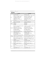
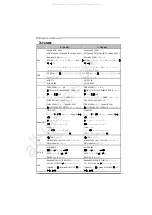
A

RABIC


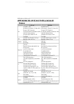
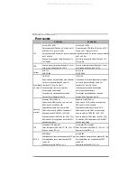
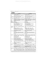
A770 A2+ 

A740X A2+ 


ﺔﺠﻟﺎﻌﻤﻟا


ةﺪﺣو

ﺔﻳﺰآﺮﻤﻟا


ﺲﺒﻘﻡ

AM2 / AM2+ 


تﺎﺠﻟﺎﻌﻡ

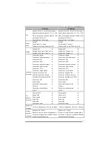
AMD Athlon 64 / Athlon 64 FX / Athlon 64 

X2 / Sempron / AM2+ 


ﺔﻴﻨﻘﺗ


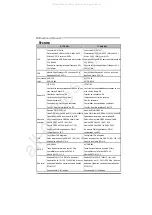
ﻦﻜﻤﺗ

AMD 64

ﺴﺏ


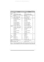
ﺔﻴﺏﻮﺳﺎﺤﻟا


تﺎﻴﻠﻤﻌﻟا


ءاﺮﺝإ


ﺔﻋﺮ

32


و

64


ﺖﺏ


ﺔﻴﻨﻘﺗ


ﻢﻋﺪﺗ

Hyper Transport

و


3.0


Cool’n’Quiet 


ﺲﺒﻘﻡ

AM2 / AM2+ 


تﺎﺠﻟﺎﻌﻡ

AMD Athlon 64 / Athlon 64 FX / Athlon 64 

X2 / Sempron / AM2+ 


ﺔﻴﻨﻘﺗ


ﻦﻜﻤﺗ

AMD 64


ﺔﻋﺮﺴﺏ


ﺔﻴﺏﻮﺳﺎﺤﻟا


تﺎﻴﻠﻤﻌﻟا


ءاﺮﺝإ


32


و

64


ﺖﺏ


ﺔﻴﻨﻘﺗ


ﻢﻋﺪﺗ

Hyper Transport

و


1.0


Cool’n’Quiet 

ﺎﻨﻟا

ﻲﺒﻥﺎﺠﻟا


ﻲﻡﺎﻡﻷا


ﻞﻗ


ﺔﻴﻨﻘﺗ


ﻢﻋﺪﺗ

HyperTransport

ﻰﻟإ


ﻞﺼﻳ


ددﺮﺘﺏ


3.0


5.2 GT/s


ﺔﻴﻨﻘﺗ


ﻢﻋﺪﺗ

HyperTransport

ﻰﻟإ


ﻞﺼﻳ


ددﺮﺘﺏ


1.0


2.0 GT/s


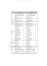
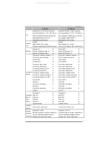
ﺢﺋاﺮﺸﻟا


ﺔﻋﻮﻤﺠﻡ


AMD 770 

AMD SB600 

AMD 740X 

AMD SB600 


ﺔﻴﺴﻴﺋﺮﻟا


ةﺮآاﺬﻟا


ﺔﺤﺘﻓ


DDR2 DIMM


دﺪﻋ

4


DIMM


ﻢﻋﺪﺗ


ةﺮآاذ


ﻦﻡ


عﻮﻥ

 DDR2


ﺔﻌﺳ


512/1024/2048 

ﺎﺠﻴﻡ


ﺖﻳﺎﺏ


و

1


ﺎﺠﻴﺝ


ﺖﻳﺎﺏ


ﺔﻌﺳ


ةﺮآاذ


ىﻮﺼﻗ


8


ﺎﺠﻴﺝ


ﺖﻳﺎﺏ


ةﺪﺣو


ةﺮآاذ

 DDR2


ﺔﺝودﺰﻡ


ةﺎﻨﻘﻟا


ﻢﻋﺪﺗ


ةﺮآاﺬﻟا


ﻦﻡ


عﻮﻥ

 DDR2


تﺎﻌﺳ

800/667/533


ﺎﺠﻴﻡ


ﺖﻳﺎﺏ


ﻢﻋﺪﺗ


ةﺮآاﺬﻟا


ﻦﻡ


عﻮﻥ

 DDR2


تﺎﻌﺳ

1066(By AM2+ CPU) 

ﺎﺠﻴﻡ


ﺖﻳﺎﺏ


ﻢﻋﺪﺗ


ﻖﺋﺎﻗر


ةﺮآاﺬﻟا

 DIMM


ﻚﻠﺗو


ﻲﺘﻟا


ﻖﻓاﻮﺘﺗ


ﻊﻡ

 ECC 

ﺔﺤﺘﻓ


DDR2 DIMM


دﺪﻋ

4


DIMM


ﻢﻋﺪﺗ


ةﺮآاذ


ﻦﻡ


عﻮﻥ

 DDR2


ﺔﻌﺳ


512/1024/2048 

ﺎﺠﻴﻡ


ﺖﻳﺎﺏ


و

1


ﺎﺠﻴﺝ


ﺖﻳﺎﺏ


ﺔﻌﺳ


ةﺮآاذ


ىﻮﺼﻗ


8


ﺎﺠﻴﺝ


ﺖﻳﺎﺏ


ةﺪﺣو


ةﺮآاذ

 DDR2


ﺔﺝودﺰﻡ


ةﺎﻨﻘﻟا


ﻢﻋﺪﺗ


ةﺮآاﺬﻟا


ﻦﻡ


عﻮﻥ

 DDR2


تﺎﻌﺳ

800/667/533


ﺎﺠﻴﻡ


ﺖﻳﺎﺏ


ﻢﻋﺪﺗ


ةﺮآاﺬﻟا


ﻦﻡ


عﻮﻥ

 DDR2


تﺎﻌﺳ

1066(By AM2+ CPU) 

ﺎﺠﻴﻡ


ﺖﻳﺎﺏ


ﻋﺪﺗ


ﻖﺋﺎﻗر


ةﺮآاﺬﻟا

 DIMM


ﻚﻠﺗو


ﻲﺘﻟا


ﻖﻓاﻮﺘﺗ


ﻊﻡ

 ECC 

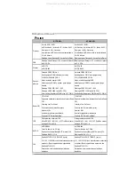
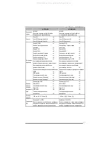
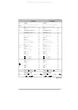
Super I/O 

ITE 8718F


ﺔﻔﻴﻇو


ﺮﻓﻮﺗ

Super I/O 

ًﺎﻡاﺪﺨﺘﺳا


ﺮﺜآﻷا


.


ﻢﻋﺪ


ﺔﻴﻨﻘﺗ


Low Pin Count Interface 

ﺔﺌﻴﺒﻟا


ﻲﻓ


ﻢﻜﺤﺘﻟا


ﻞﺋﺎﺳو

:


ةﺰﻬﺝﻷا


ﺔﻟﺎﺣ


ﺔﻓﺮﻌﻤﻟ


ﺐﻗاﺮﻡ


ﺔﺣوﺮﻤﻟا


ﺔﻋﺮﺳ


ﻲﻓ


ﺐﻗاﺮﻡ


ﺔﻔﻴﻇو

"Smart Guardian"


ﻦﻡ


ITE 

ITE 8718F


ﺔﻔﻴﻇو


ﺮﻓﻮﺗ

Super I/O 

ًﺎﻡاﺪﺨﺘﺳا


ﺮﺜآﻷا


.


ﻢﻋﺪ


ﺔﻴﻨﻘﺗ


Low Pin Count Interface 

ﺔﺌﻴﺒﻟا


ﻲﻓ


ﻢﻜﺤﺘﻟا


ﻞﺋﺎﺳو

:


ةﺰﻬﺝﻷا


ﺔﻟﺎﺣ


ﺔﻓﺮﻌﻤﻟ


ﺐﻗاﺮﻡ


ﺔﺣوﺮﻤﻟا


ﺔﻋﺮﺳ


ﻲﻓ


ﺐﻗاﺮﻡ


ﺔﻔﻴﻇو

"Smart Guardian"


ﻦﻡ


ITE 


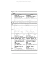
ﺬﻔﻨﻡ

IDE  


ﻢﻜﺤﺘﻡ

IDE

ﻞﻡﺎﻜﺘﻡ


ﺔﻴﻨﻘﺘﺏ


ﻞﻗﺎﻥ

Ultra DMA 33 / 66 / 100 / 133 

ﻲﺴﻴﺋر


ﻊﺿو


ﻊﺿو


ﻢﻋد

PIO Mode 0~4 


ﻢﻜﺤﺘﻡ

IDE

ﻞﻡﺎﻜﺘﻡ


ﺔﻴﻨﻘﺘﺏ


ﻞﻗﺎﻥ

Ultra DMA 33 / 66 / 100 / 133 

ﻲﺴﻴﺋر


ﻊﺿو


ﻊﺿو


ﻢﻋد

PIO Mode 0~4 

SATA II 

AMD SB600 


ﻰﻟإ


ﻞﺼﺗ


تﺎﻋﺮﺴﺏ


تﺎﻥﺎﻴﺒﻟا


ﻞﻘﻥ

3


ﺖﺏﺎﺠﻴﺝ

/

ﺔﻴﻥﺎﺙ

.


تﺎﻔﺹاﻮﻤﻟ


ﺔﻘﺏﺎﻄﻡ

SATA


راﺪﺹﻹا


 2.0. 


ﺔﻴﻨﻘﺗ


ﻢﻋﺪﺗ

RAID 0,1,1+0 

AMD SB600 

ﺎﻥﺎﻴﺒﻟا


ﻞﻘﻥ


ﻰﻟإ


ﻞﺼﺗ


تﺎﻋﺮﺴﺏ


ت

3


ﺖﺏﺎﺠﻴﺝ

/

ﺔﻴﻥﺎﺙ

.


تﺎﻔﺹاﻮﻤﻟ


ﺔﻘﺏﺎﻄﻡ

SATA


راﺪﺹﻹا


 2.0. 


ﺔﻴﻨﻘﺗ


ﻢﻋﺪﺗ

RAID 0,1,1+0 

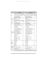
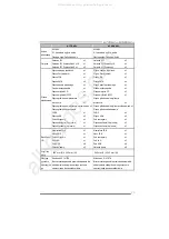
ﺔﻴﻠﺥاد


ﺔﻜﺒﺵ


Realtek RTL8111C /RTL8102E

)

يرﺎﻴﺘﺥا

(


ضوﺎﻔﺗ


ﻲﺋﺎﻘﻠﺗ


10

/

100


ﺎﺠﻴﻡ


ﺖﻳﺎﺏ


 /

ﺔﻴﻥﺎﺙ


و

1

ﺎﺠﻴﺝ


ﺖﺏ

/

ﺔﻴﻥﺎﺙ


قﺎﻄﻨﻟا


يددﺮﺘﻟا


ﺖﺏﺎﺠﻴﺠﻠﻟ


رﻮﺼﻘﻡ


ﻂﻘﻓ


ﻰﻠﻋ

 Realtek 

RTL8111C 

ﻴﻥﺎﻜﻡإ


ﻞﻘﻨﻟا


جودﺰﻤﻟا


ﻞﻡﺎﻜﻟا

/

ﻲﻔﺼﻨﻟا


Realtek RTL8102E /RTL8111C

)

يرﺎﻴﺘﺥا

(


ضوﺎﻔﺗ


ﻲﺋﺎﻘﻠﺗ


10

/

100


ﺎﺠﻴﻡ


ﺖﻳﺎﺏ


 /

ﺔﻴﻥﺎﺙ


و

1

ﺎﺠﻴﺝ


ﺖﺏ

/

ﺔﻴﻥﺎﺙ


قﺎﻄﻨﻟا


يددﺮﺘﻟا


ﺖﺏﺎﺠﻴﺠﻠﻟ


رﻮﺼﻘﻡ


ﻂﻘﻓ


ﻰﻠﻋ

 Realtek 

RTL8111C 

ﺔﻴﻥﺎﻜﻡإ


ﻞﻘﻨﻟا


جودﺰﻤﻟا


ﻞﻡﺎﻜﻟا

/

ﻲﻔﺼﻨﻟا


All manuals and user guides at all-guides.com

Содержание A740X-A2+

Страница 1: ...ular installation The vendor makes no representations or warranties with respect to the contents here andspecially disclaims any implied warranties of merchantability or fitness for any purpose Further the vendor reserves the right to revise this publication and to make changes to the contents here without obligation to notify any party beforehand Duplication of this publication in part or in whol...

Страница 2: ...rs and Slots 10 Chapter 3 Headers Jumpers Setup 13 3 1 How to Setup Jumpers 13 3 2 Detail Settings 13 Chapter 4 RAID Functions 21 4 1 Operation System 21 4 2 Raid Arrays 21 4 3 How RAID Works 21 Chapter 5 Useful Help 24 5 1 Driver Installation Note 24 5 2 Award BIOS Beep Code 25 5 3 Extra Information 25 5 4 Troubleshooting 26 Appendencies SPEC In Other Language 28 German 28 France 30 Italian 32 Sp...

Страница 3: ...e components on motherboard or the rear side of the board unless necessary Hold the board on the edge do not try to bend or flex the board Do not leave any unfastened small parts inside the case after installation Loose parts will cause short circuits which may damage the equipment Keep the computer from dangerous area such as heat source humid air and water 1 2 PACKAGE CHECKLIST HDD Cable X 1 Ser...

Страница 4: ... 512 1024 2048MB DDR2 Max Memory Capicity 8GB Dual Channel Mode DDR2memorymodule Supports DDR2 533 667 800 Supports DDR2 1066 byAM2 CPU Registered DIMM and ECC DIMM is not supported DIMM Slots x 4 Each DIMM supports 512 1024 2048MB DDR2 Max Memory Capicity 8GB Dual Channel Mode DDR2memorymodule Supports DDR2 533 667 800 Supports DDR2 1066 byAM2 CPU Registered DIMM and ECC DIMM is not supported IDE...

Страница 5: ...header x1 USB connector x2 USB connector x2 Serial port Connector x1 Serial port Connector x1 Power Connector 24pin x1 Power Connector 24pin x1 On Board Connector Power Connector 4pin x1 Power Connector 4pin x1 Back Panel I O PS 2Keyboard x1 PS 2 Mouse x1 SerialPort x1 LAN port x1 USB Port x6 Audio Jack x3 PS 2Keyboard x1 PS 2 Mouse x1 SerialPort x1 LAN port x1 USB Port x6 Audio Jack x3 BoardSize ...

Страница 6: ...MOS1 JPANEL IDE JATXPWR24 CPUFAN SYSFAN DIMMB1 DIMMB2 DIMMA2 Socket A M2 PCIE_X16 PCIE_X1_2 PCI3 PCI2 AMD 770 740X SATA4 JAU DI O F JUSBLAN SATA3 SATA2 SATA1 JUSB2 J U SB4 BIOS PCI1 JCOM 2 AMD SB600 LAN JAUDIO JK BV1 JUS BV1 JUSB V3 JC OM1 JUS BV 2 Note represents the 1 st pin All manuals and user guides at all guides com a l l g u i d e s c o m ...

Страница 7: ...ection cap Step 2 Pull the lever toward direction Afrom the socket and then raise the lever up to a 90 degree angle Step 3 Look for the white triangle on socket and the gold triangle on CPU should point towards this white triangle The CPU will fit only in the correct orientation All manuals and user guides at all guides com ...

Страница 8: ...PUFAN This completes the installation Note Please update the BIOS to the latest version while using AM2 CPUs Due to the latest CPU transition you mayencounter the situation that the newsystem failed to boot while using new AM2 CPUs In this case please install one standar d AM2 CPU to boot your system and update the latest BIOS from our website for AM2 CPUs support All manuals and user guides at al...

Страница 9: ...an Header Pin Assignment 1 Ground 2 12V 3 FAN RPM rate sense 1 4 4 Smart Fan Control By Fan SYSFAN System Fan Headers Pin Assignment 1 Ground 2 12V 1 3 3 FAN RPM rate sense Note The CPUFAN and SYSFAN support 4 pin and 3 pin head connector When connecting with wires onto connectors please note that the red wire is the positive and should be connected to pin 2 and the black wire is Ground and should...

Страница 10: ...IMM slot by pressing the retaining clips outward Align a DIMM on the slot such that the notch on the DIMM matches the break on the Slot 2 Insert the DIMM vertically and firmly into the slot until the retaining chip snap back in place and the DIMM is properly seated All manuals and user guides at all guides com ...

Страница 11: ...al Channelf unction of the motherboard the memory module must meet the following requirements Install memory module of the same density in pairs shown in thef ollowing table Dual Channel Status DIMMA1 DIMMB1 DIMMA2 DIMMB2 Enabled O O X X Enabled X X O O Enabled O O O O O means memory installed X means memory not installed The DRAM bus width of the memory module must be the same x8 or x16 All manua...

Страница 12: ...es This connector supports the prov idedf loppy drive ribbon cables 1 33 2 34 IDE Hard Disk Connector The motherboard has a 32 bit Enhanced IDE Controller that prov ides PIO Mode 0 4 Bus Master and Ultra DMA 33 66 100 133f unctionality The IDE connector can connect a master and a slave drive soy ou can connect up to two hard disk driv es 1 39 2 40 All manuals and user guides at all guides com ...

Страница 13: ... 5 0Gb s on the data pins 2X bandwidth ov er the PCI Express 1 0 architecture PCIE_X16 PCI Express x16 Slot for A740X A2 PCI Express 1 0a compliant Maximum theoretical realized bandwidth of 4GB s simultaneously per direction f or an aggregate of 8GB s totally PCIE_X1_1 PCIE_X1_2 PCI Express x1Slots for A740X A2 PCI Express 1 0a compliant Data transf er bandwidth up to 250MB s per direction 500MB s...

Страница 14: ...nnect Slots This motherboard is equipped with 3 standard PCI slots PCI stands f or Peripheral Component Interconnect and it is a bus standard for expansion cards This PCI slot is designated as 32 bits PCI1 PCI3 PCI2 All manuals and user guides at all guides com ...

Страница 15: ...connector includes Power on Reset HDD LED Power LED and speaker connection It allows user to connect the PC case s front panel switch f unctions PWR_LED On Off RST HLED SPK 1 9 16 8 Pin Assignment Function Pin Assignment Function 1 5V 9 N A 2 N A 10 N A N A 3 N A 11 N A N A 4 Speaker Speaker Connector 12 Power LED 5 HDD LED 13 Power LED 6 HDD LED Hard drive LED 14 Power LED Power LED 7 Ground 15 P...

Страница 16: ...V 2 3 3V 15 Ground 3 Ground 16 PS_ON 4 5V 17 Ground 5 Ground 18 Ground 6 5V 19 Ground 7 Ground 20 NC 8 PW_OK 21 5V 9 StandbyVoltage 5V 22 5V 10 12V 23 5V 11 12V 24 Ground 12 3 3V JATXPWR4 ATX Power Source Connector By connecting this connector it will provide 12V to CPU power circuit Pin Assignment 1 12V 2 12V 3 Ground 1 2 3 4 4 Ground All manuals and user guides at all guides com a l l g u i d e ...

Страница 17: ...4 USB 5 USB 6 USB 7 Ground 8 Ground 9 Key 1 2 9 10 USB3 USB4 10 NC JAUDIOF Front Panel Audio Header This header allows user to connect the front audio output cable with the PC f ront panel This header allows only HD audio front panel connector AC 97 connector is not acceptable Pin Assignment 1 Mic Left in 2 Ground 3 Mic Right in 4 GPIO 5 Right line in 6 Jack Sense 7 Front Sense 8 Key 9 Left line i...

Страница 18: ...cing the jumper on pin2 3 it allows user to restore the BIOS saf e setting and the CMOS data please carefully f ollow the procedures to avoid damaging the motherboard 1 3 Pin 1 2 Close Normal Operation default 1 3 1 3 Pin 2 3 Close Clear CMOS data Clear CMOS Procedures 1 Remov e AC power line 2 Set the jumper to Pin 2 3 close 3 Wait f orf ive seconds 4 Set the jumper to Pin 1 2 close 5 Power on th...

Страница 19: ...5 Pin Assignment Pin Assignment 1 Strobe 14 Ground 2 ALF 15 Data 6 3 Data 0 16 Ground 4 Error 17 Data 7 5 Data 1 18 Ground 6 Init 19 ACK 7 Data 2 20 Ground 8 Scltin 21 Busy 9 Data 3 22 Ground 10 Ground 23 PE 11 Data 4 24 Ground 12 Ground 25 SCLT 13 Data 5 26 Key All manuals and user guides at all guides com ...

Страница 20: ...the SATA 2 0 spec and with transfer rate of 3 0Gb s Pin Assignment 1 Ground 2 TX 3 TX 4 Ground 5 RX 6 RX 1 4 7 SATA4 SATA1 SATA3 SATA2 7 Ground JSPDIF_OUT Digital Audio out Connector This connector allows user to connect the PCI bracket SPDIF output header Pin Assignment 1 5V 2 SPDIF_OUT 1 3 3 Ground All manuals and user guides at all guides com ...

Страница 21: ... Transmitted data 4 Data terminal ready 5 Signal ground 6 Data set ready 7 Request to send 8 Clear to send 9 Ring indicator 10 Key 1 2 9 10 JKBV1 Power Source Header for PS 2 Keyboard and Mouse 3 1 Pin 1 2 Close 5V for PS 2 keyboard and mouse 1 3 3 1 Pin 2 3 close 5V STB for PS 2 keyboard and mouse All manuals and user guides at all guides com a l l g u i d e s c o m ...

Страница 22: ...V for USB ports at JUSB2 JUSBV1 5V for USB ports at f ront panel JUSB3 JUSB4 Pin 2 3 Close JUSBV3 5V STB for USB ports at JUSB1 JUSBLAN JUSBV2 5V STB for USB ports at JUSB2 JUSBV1 5V STB for USB ports at f ront panel JUSB3 JUSB4 1 3 Pin 1 2 close 1 3 1 3 JUSBV2 JUSBV1 JUSBV3 1 3 1 3 Pin 2 3 close All manuals and user guides at all guides com ...

Страница 23: ...writes across multiple drives in parallel The size of each block is determined by the stripe size parameter which you set during the creation ofthe RAID set based on the systemenvironment This technique reduces overall disk access time and offers high bandwidth Features and Benefits Drives Minimum 1 and maximum is up to 6 or 8 Depending on the platf orm Uses Intended for non critical data requirin...

Страница 24: ...y solutions or as a form of automatic backup that eliminates tedious manual backups to more expensive and less reliable media Features and Benefits Drives Minimum 2 and maximum is 2 Uses RAID 1 is idealf or small databases or any other application that requires f ault tolerance and minimal capacity Benefits Prov ides 100 data redundancy Should one driv ef ail the controller switches to the other d...

Страница 25: ...he platform Benefits Optimizes for both fault tolerance and perf ormance allowing for automatic redundancy May be simultaneously used with other RAID lev els in an array and allows for spare disks Drawbacks Requires twice the available disk spacef or data redundancy the same as RAID level 1 Fault Tolerance Yes Block 1 Block 3 Block 5 Block 2 Block 4 Block 6 Block 1 Block 3 Block 5 Block 2 Block 4 ...

Страница 26: ...lick on the Driver icon The setup guide will list the compatible driver for your motherboard and operating system Click on each device driver to launch the installation program B Software Installation To install the software please click on the Software icon The setup guide will list the software available for your system click on each software title to launch the installation program C Manual Asi...

Страница 27: ...s been activated When the CPU is over heated the motherboard will shutdown automatically to avoid a damage of the CPU and the system may not power on again In this case please double check 1 The CPU cooler surface is placed evenly with the CPU surface 2 CPU fan is rotated normally 3 CPU fan speed is fulfilling with the CPU speed After confirmed please follow steps below to relief the CPU protectio...

Страница 28: ... Make sure both ends are securely plugged in check the driv e type in the standard CMOS setup 2 Backing up the hard drive is extremely important All hard disks are capable of breaking down at any time System only boots f rom optical driv e Hard disk can be read and applications can be used but booting from hard disk is impossible 1 Back up data and applications f iles 2 Ref ormat the hard driv e R...

Страница 29: ...A770 A2 A740X A2 27 This page is intentionally left blank All manuals and user guides at all guides com ...

Страница 30: ...ndeten altenSuper E A Funktionen Low Pin Count Schnittstelle Umgebungskontrolle Hardware Überwachung Lüfterdrehzahl Controller Smart Guardian Funktion vonITE Arbeitsspeich er DDR2 DIMM Steckplätze x 4 Jeder DIMM unterstützt 512 1024 2048MB DDR2 Max 8GB Arbeitsspeicher Dual Kanal DDR2 Speichermodul Unterstützt DDR2 533 667 800 Unterstützt DDR2 1066 by AM2 CPU registrierte DIMMs ECC DIMMs werden nic...

Страница 31: ...nt Audioanschluss x1 CD IN Anschluss x1 CD IN Anschluss x1 S PDIF Ausgangsanschluss x1 S PDIF Ausgangsanschluss x1 CPU Lüfter Sockel x1 CPU Lüfter Sockel x1 System Lüfter Sockel x1 System Lüfter Sockel x1 CMOS löschen Sockel x1 CMOS löschen Sockel x1 USB Anschluss x2 USB Anschluss x2 Serieller Anschluss x1 Serieller Anschluss x1 Stromanschluss 24 polig x1 Stromanschluss 24 polig x1 Onboard Ans chl...

Страница 32: ...tales Moniteur de matériel Contrôleur de vitesse de ventilateur Fonction Gardienintelligent de l ITE Mémoire principale Fentes DDR2DIMM x 4 Chaque DIMM prend encharge des DDR2 de 512 1024 2048 Mo Capacitémémoire maximale de 8 Go Module de mémoireDDR2 àmodeà double voie Prend encharge la DDR2 533 667 800 Prend encharge la DDR2 1066 by AM2 CPU Les DIMM à registres et DIMM avec code correcteurs d err...

Страница 33: ...neau avant x1 Connecteur Audio du panneau avant x1 Connecteur Audio du panneau avant x1 Connecteur d entréeCD x1 Connecteur d entréeCD x1 Connecteur desortie S PDIF x1 Connecteur desortie S PDIF x1 Embase de ventilateurUC x1 Embase de ventilateurUC x1 Embase de ventilateursystème x1 Embase de ventilateursystème x1 Embase d effacement CMOS x1 Embase d effacement CMOS x1 Connecteur USB x2 Connecteur...

Страница 34: ...ount Funzioni di controllo dell ambiente Monitoraggio hardware Controller velocità ventolina Funzione Smart Guardian di ITE Memoria principale Alloggi DIMM DDR 2 x 4 Ciascun DIMM supporta DDR 2 512 1024 2048MB Capacità massima della memoria 8GB Modulo di memoria DDR2 a canale doppio Supporto di DDR2 533 667 800 Supporto di DDR2 1066 by AM2 CPU DIMM registrati e DIMM ECC non sono supportati Alloggi...

Страница 35: ...ntale x1 Connettore CD in x1 Connettore CD in x1 Connettore output SPDIF x1 Connettore output SPDIF x1 Collettore ventolina CPU x1 Collettore ventolina CPU x1 Collettore ventolina sistema x1 Collettore ventolina sistema x1 Collettore cancellazione CMOS x1 Collettore cancellazione CMOS x1 Connettore USB x2 Connettore USB x2 Porta seriale x1 Porta seriale x1 Connettore alimentazione x1 24 pin Connet...

Страница 36: ...te de ITE Memoria principal Ranuras DIMM DDR2 x 4 Cada DIMM admite DDR de 512 1024 2048MB Capacidadmáxima de memoria de 8GB Módulo dememoria DDR2 de canal Doble Admite DDR2 de 533 667 800 Admite DDR2 de 1066 byAM2 CPU No admite DIMM registrados o DIMM compatibles con ECC Ranuras DIMM DDR2 x 4 Cada DIMM admite DDR de 512 1024 2048MB Capacidadmáxima de memoria de 8GB Módulo dememoria DDR2 de canal D...

Страница 37: ... X1 Cabecera de ventilador de CPU X1 Cabecera de ventilador desistema X1 Cabecera de ventilador desistema X1 Cabecera de borrado de CMOS X1 Cabecera de borrado de CMOS X1 Conector USB X2 Conector USB X2 Puerto serie X1 Puerto serie X1 Conector de alimentación X1 24 patillas Conector de alimentación X1 24 patillas Conectores en placa Conector de alimentación X1 4 patillas Conector de alimentación X...

Страница 38: ...LPC Low Pin Count Iniciativas para controlo doambiente Monitorização do hardware Controlador davelocidade daventoinha Função Smart Guardian da ITE Memória principal Ranhuras DIMM DDR2 x 4 Cada módulo DIMM suporta umamemória DDR2 de 512 1024 2048 MB Capacidade máxima dememória 8GB Módulo dememória DDR2 de canal duplo Suportamódulos DDR2 533 667 800 Suportamódulos DDR2 1066 by AM2 CPU Os módulos DIM...

Страница 39: ...frontal x1 Conector de áudio frontal x1 Conector para entrada de CDs x1 Conector para entrada de CDs x1 Conector desaída S PDIF x1 Conector desaída S PDIF x1 Conector da ventoinha da CPU x1 Conector da ventoinha da CPU x1 Conector da ventoinha dosistema x1 Conector da ventoinha dosistema x1 Conector para limpeza do CMOS x1 Conector para limpeza do CMOS x1 Conector USB x2 Conector USB x2 Porta séri...

Страница 40: ...a DDR2 1066 by AM2 CPU Brak obsługi Registered DIMM oraz ECC DIMM SuperI O ITE 8718F Zapewnia najbardziej powszechne funkcjeSuper I O Interfejs Low PinCount Funkcje kontroliwarunków pracy Monitor H W Kontroler prędkościwentylatora Funkcja ITE Smart Guardian ITE 8718F Zapewnia najbardziej powszechne funkcjeSuper I O Interfejs Low PinCount Funkcje kontroliwarunków pracy Monitor H W Kontroler prędkoś...

Страница 41: ...sora x1 Złącze główkowe wentylatorasystemowego x1 Złącze główkowe wentylatorasystemowego x1 Złącze główkowe kasowania CMOS x1 Złącze główkowe kasowania CMOS x1 Złącze USB x2 Złącze USB x2 Port szeregowy x1 Port szeregowy x1 Złączezasilania 24 pinowe x1 Złączezasilania 24 pinowe x1 Złącza wbudowane Złączezasilania 4 pinowe x1 Złączezasilania 4 pinowe x1 Back Panel I O Klawiatura PS 2 x1 Mysz PS 2 x...

Страница 42: ...ствующиефункциональные возможности SuperI O Интерфей с с ни зким количеством выводов Инициативы по охране окружающейсреды Аппаратный монитор Регуляторскорости ФункцияITE Smart Guardian Интеллектуальнаязащита ITE 8718F Обеспечивает наиболее и спользуемые действующиефункциональные возможности SuperI O Интерфей с с ни зким количеством выводов Инициативы по охране окружающейсреды Аппаратный монитор Ре...

Страница 43: ...ее при способление вентилятора си стемы x1 Контактирующее при способление вентилятора си стемы x1 Открытое контактирующее при способление CMOS x1 Открытое контактирующее при способление CMOS x1 USB разъём x2 USB разъём x2 Последовательный порт x1 Последовательный порт x1 Разъем питания 24 вывод x1 Разъем питания 24 вывод x1 Встроенны й разъём Разъем питания 4 вывод x1 Разъем питания 4 вывод x1 Зад...

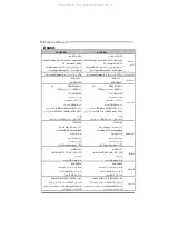
Страница 44: ... 667 533 ﻡﻴﺠﺎ ﺏﺎﻳﺖ ﺗﺪﻋﻢ اآﺮة ﺬ اﻟ ﻡﻦ ﻥﻮع DDR2 ﺳﻌﺎت 1066 ByAM2 CPU ﻡﻴﺠﺎ ﺏﺎﻳﺖ ﻻ ﺗﺪﻋ ﻢ رﻗﺎﺋﻖ اآﺮة ﺬ اﻟ DIMM وﺗﻠﻚ اﻟﺘﻲ ﻻ ﺗﺘﻮاﻓﻖ ﻡﻊ ECC SuperI O ITE 8718F وﻇﻴﻔﺔ ﺗﻮﻓﺮ Super I O ً ﺎ اﺳﺘﺨﺪاﻡ اﻷآﺜﺮ ﺗ ﺪﻋﻢ ﺗﻘﻨﻴﺔ LowPin CountInterface ﻟﺒﻴﺌﺔ ا ﻓﻲ ﻟﺘﺤﻜﻢ ا وﺳﺎﺋﻞ اﻷﺝﻬﺰة ﻟﺔ ﺎ ﺣ ﻟﻤﻌﺮﻓﺔ ﻡﺮاﻗﺐ ﻟﻤﺮوﺣﺔ ا ﺳﺮﻋﺔ ﻓﻲ ﻡﺮاﻗﺐ وﻇﻴﻔﺔ Smart Guardian ﻡﻦ ITE ITE 8718F وﻇﻴﻔﺔ ﺗﻮﻓﺮ Super I O ً ﺎ اﺳﺘﺨﺪاﻡ اﻷآﺜﺮ ﺗ ﺪﻋﻢ ﺗﻘﻨﻴﺔ LowPin CountI...

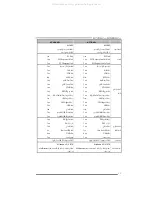
Страница 45: ...وﺣﺪة ﻡﺮوﺣﺔ وﺹﻠﺔ ﻋﺪد 1 اﻟﻨﻈﺎم ﻡﺮوﺣﺔ وﺹﻠﺔ ﻋﺪد 1 اﻟﻨﻈﺎم ﻡﺮوﺣﺔ وﺹﻠﺔ ﻋﺪ 1 ﻡﺴﺢ وﺹﻠﺔ CMOS ﻋﺪد 1 و ﻡﺴﺢ ﺹﻠﺔ CMOS ﻋﺪد 1 ﻡﻨﻔﺬ USB ﻋﺪد 2 ﻡﻨﻔﺬ USB ﻋﺪد 2 ﺗﺴﻠﺴﻠﻲ ﻡﻨﻔﺬ ﻋﺪد 1 ﺗﺴﻠﺴﻠﻲ ﻡﻨﻔﺬ ﻋﺪد 1 اﻟﻄﺎﻗﺔ ﺗﻮﺹﻴﻞ ﻡﻨﻔﺬ 24 دﺏﻮس ﻋﺪد 1 اﻟﻄﺎﻗﺔ ﺗﻮﺹﻴﻞ ﻡﻨﻔﺬ 24 دﺏﻮس ﻋﺪد 1 اﻟﻤﻨﺎﻓﺬ ﺳﻄﺢ ﻋﻠﻰ اﻟﻠﻮﺣﺔ اﻟﻄﺎﻗﺔ ﺗﻮﺹﻴﻞ ﻡﻨﻔﺬ 4 دﺏﺎﺏﻴﺲ ﻋﺪد 1 اﻟﻄﺎﻗﺔ ﺗﻮﺹﻴﻞ ﻡﻨﻔﺬ 4 دﺏﺎﺏﻴﺲ ﻋﺪد 1 دﺥﻞ ﻡﻨﺎﻓﺬ ﺥﺮج ﻟﺨﻠﻔ ا اﻟﻠﻮﺣﺔ ﻴﺔ ﻡﻔﺎﺗﻴﺢ ﻟﻮﺣﺔ PS 2 ﻋﺪد 1 ﻡﺎوس PS 2 ﻋﺪد 1 ﺗ...

Страница 46: ...B デュアル チャンネルモードDDR2メモリモジュール DDR2 533 667 800をサポート DDR2 1066をサポート byAM2 CPU 登録済みDIMMとECC DIMMはサポートされません SuperI O ITE 8718F もっとも一般に使用されるレガシーSuper I O機能を 採用しています 低ピンカウントインターフェイス 環境コントロールイニシアチブ H Wモニター ファン速度コントローラ モニター ITEの スマートガーディアン 機能 ITE 8718F もっとも一般に使用されるレガシーSuper I O機能を 採用しています 低ピンカウントインターフェイス 環境コントロールイニシアチブ H Wモニター ファン速度コントローラ モニター ITEの スマートガーディアン 機能 IDE 統合IDEコントローラ Ultra DMA 33 66 100 133 バスマス...

Страница 47: ...CDインコネクタ x1 CDインコネクタ x1 S PDIFアウトコネクタ x1 S PDIFアウトコネクタ x1 CPUファンヘッダ x1 CPUファンヘッダ x1 システムファンヘッダ x1 システムファンヘッダ x1 CMOSクリアヘッダ x1 CMOSクリアヘッダ x1 USBコネクタ x2 USBコネクタ x2 シリアルポート x1 シリアルポート x1 電源コネクタ 24ピン x1 電源コネクタ 24ピン x1 オンボードコ ネクタ 電源コネクタ 4ピン x1 電源コネクタ 4ピン x1 背面パネル I O PS 2キーボード x1 PS 2マウス x1 シリアルポート x1 LANポート x1 USBポート x6 オーディオジャック x3 PS 2キーボード x1 PS 2マウス x1 シリアルポート x1 LANポート x1 USBポート x6 オーディオジャック x3 ボ...

Отзывы: