77-2019-R4.2 (8/2017)
4 / 8
EN
www.carlisleft.com
Approx. Air Consumption SCFM
with Specific Dynamic Air
Presure (PSI) at air cap
GUN MOUNTING
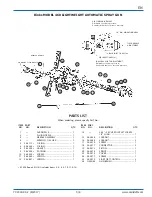
A hexagon screw (13) will secure the spray gun to the 54-380 gun
mounting rod. For special mountings, a 1/2" dia. rod will fir the hole
in the top of the gun body.
HOSE LENGTH
Install minimum hose length from valve to gun to minimize time
required for “off–on” response of gun.
CONNECTIONS
The air connection and fluid connection are both 1/4 NPS. The air con-
nection is stamped “a”.
AIR SUPPLY
Since the gun has its own control, atomizing air may be taken directly
from the main line. However, if regulated air is used, 50 PSI minimum
is required to actuate gun fluid valve piston. When rapid “off–on” oper-
ation is required, use a 3-way valve which exhausts to atmosphere, in
place of a 2-way valve.
SPRAY PATTERN
The width of spray pattern is controlled by the control assembly (26).
Vertical or horizontal position of the spray is obtained by rotating the
air nozzle.
ATOMIZATION
Air volume to the nozzle is controlled by the control assembly (26)
located adjacent to the air inlet connection.
FLUID CONTROL
The rate of fluid flow is controlled by a combination of the selection
of the correct nozzle orifice size and adjustment of fluid pressure. The
maximum fluid flow rate is approximately 8 fluid ounces per minute.
Fine adjustment of the fluid flow can be obtained by controlling the
travel of the needle valve. Clockwise rotation of the screw (24) decreases
the needle travel and counterclockwise rotation increases the travel.
The locknut (15) is used to lock the screw (24) after adjustment.
FAULTY SPRAY
Caused by improper cleaning, or dried fluid on nozzle tip or in the air
nozzle. Soak these parts in solvent to soften the dried fluid and remove
with a brush or cloth.
If either air nozzle or fluid nozzle is damaged, the part must be replaced
before a perfect spray can be obtained.
SPITTING
To eliminate spitting and dripping, turn on atomizing air before turning
on fluid.
NEEDLE ADJUSTMENT
The correct setting is to allow approximately 1/16" piston travel before
contacting NEEDLE. Adjustment is made by loosening the screw (17)
on rear of needle and rotating the spring guide (20) either forward to
reduce or back to increase clearance.
AIR LEAKAGE INTO AIR CYLINDER VENT
Remove piston (19) and inspect for dirt or damage to large o-ring (5).
Clean piston and cylinder. Replace o-ring if necessary. Lubricate with
white petroleum jelly.
AIR LEAKAGE AT FLUID NEEDLE
Remove piston (19) and inspect for dirt or damage to small o-ring (6).
Replace if necessary.
FLUID LEAKAGE AT PACKING GLAND
Tighten screw (10) and slightly “back-off” screw to set packing. If leakage
continues, replace packing.
CLEANING THE GUN
Under no circumstances should the complete gun be immersed in thin-
ners or solvents.
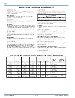
INSTALLATION, OPERATION & MAINTENANCE
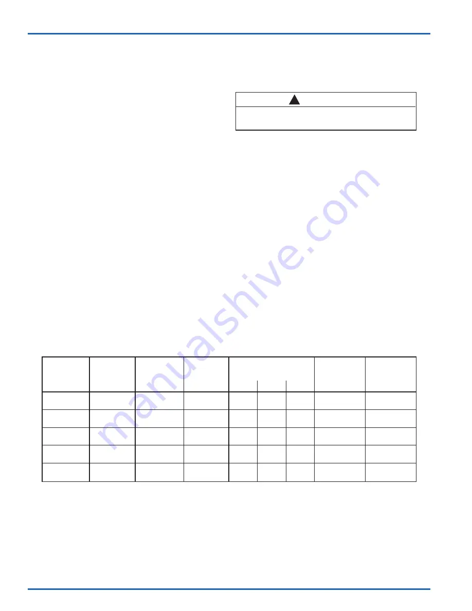
Binks MODEL 460 GUN FLUID NOZZLE, NEEDLE & AIR CAP SELECTION CHART
Type of
*Max. Spray
Spray
Pattern Size @
Fluid Nozzle
Orifice Size
Fluid Needle
Air Nozzle
30 PSI
50 PSI
70 PSI
Pattern
5" Distance
J920SS
.020"
940
J92P
ELLIPSE /
(PN 45-84)
(.5 mm)
(PN 47-454)
(PN 46-131)
6.4 8.5 10.5
STRAIGHT SIDES
6"
J930SS
.030"
940
J92P
ELLIPSE /
(PN 45-85)
(.75 mm)
(PN 47-454)
(PN 46-131)
6.4 8.5 10.5
STRAIGHT SIDES
7.5"
J940SS
.040"
940
J92P
ELLIPSE /
(PN 45-86)
(1.0 mm)
(PN 47-454)
(PN 46-131)
6.4 8.5 10.5
STRAIGHT SIDES
8"
J940SS .040"
940
J92R
(PN 45-86)
(1.0 mm)
(PN 47-454)
(PN 46-126)
4 6 8
ROUND
2"
K960SS
.060"
960
K92P
ELLIPSE /
(PN 45-87)
(1.5 mm)
(PN 47-455)
(PN 46-134)
7.2 10.6 14
STRAIGHT SIDES
9.5"
*Spray pattern for reference only. Pattern size will vary slightly with flow and viscosity of the materials.
CAUTION
Never use metal instruments to clean air or fluid nozzles.
These parts are carefully machined and any damage to them
will cause a faulty spray.
!


