CLEANING THE GUN—WHEN
USED WITH PRESSURE TANK:
Shut off the air supply to the Pressure
Tank and release the pressure in the tank.
Hold a piece of cloth over the gun nozzle
and pull the trigger, the air will back up
through the fluid nozzle and force the
fluid out of the hose and into the tank.
Remove paint from tank, clean tank and
put enough compatible solvent into the
tank to clean the hose and gun thoroughly.
Spray this through the gun until it is clean,
then blow out the fluid hose to dry it and
remove all traces of materials by attaching
it to the air line.
WHEN USED WITH A CUP:
A compatible solvent should be siphoned
through gun by inserting tube from siphon
cup in an open container of solvent.
Trigger gun intermittently to thoroughly
flush passageways and internal parts.
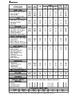
HOW TO USE THE CHART
A.MATERIAL TO BE SPRAYED
Select the type of fluid you want to
spray or a fluid which has the same
characteristics as one of those listed.
B.METHOD OF FEEDING MATERIAL
TO THE GUN
Fluid Nozzle—Consider the speed of
application and the viscosity of the fluid
to be sprayed. Refer to the Fluid Nozzle
Orifice Size Chart, below.
Air Nozzle—Choice is determined by
the type of fluid to be sprayed and the
volume of air available for the gun.
• External Mix Nozzles, which are
generally used, accomplish atomiza-
tion outside the nozzle. Spray patterns
are adjustable from round to fan
with all intermediate patterns.
(Designated by the letter “E”).
• Siphon Type External Mix Nozzles,
designated by the letter “S”, will
siphon the material from a cup.
Used generally for refinished and
touch-up work which does not
require large quantities of paint.
• Pressure Type External Mix Nozzles,
designated by the letter “P”, require
pressure to feed the material to the
nozzle. A pressure cup, pressure
tank or pump is necessary. Used for
production work and where large
quantities of fluid are handled. This
type of nozzle has a greater range of
fluid flow and does not limit the size
of the paint container.
• Internal Mix Nozzles mix the air and
fluid within the air nozzle. The spray
pattern is determined by the shape of
the nozzle and cannot be changed.
Internal mix nozzles require less air
and produce slightly less fog. Pressure
equipment must be used with this type
of nozzle. Recommended for mainte-
nence spraying of heavy materials
where a fine finish is not required.
(Designated by the letter “I”).
C. VOLUME OF AIR (CFM REQUIRED)
The cubic feet per minute (CFM) listed
at 30, 50 and 70 PSI is the actual air
used by the air nozzle. increase of pres-
sure subsequently increases volume of
air required by air nozzle, or vice versa.
Assume that a compressor will produce
3-5 CFM per horsepower.
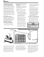
It is extremely poor practice to mount the
oil and water extractor on or even near
the compressor unit. The temperature of
the air is greatly increased as it passes
through the compressor and this com-
pressed air must be cooled before the
moisture in it will condense. if the air
from the compressor is still warm when
it passes through the oil and water extrac-
tor, moisture will not be effectively
removed, but will remain in suspension.
Then, when the air cools in the hoe beyond
the extractor, the moisture will condense
into drops of water and cause trouble.
Air lines must be properly drained.
Pitch all air lines back towards the
compressor so that condensed moisture
will flow back into the air receiver where
it can be removed by opening a drain.
Every low point on an air line acts as a
water trap. Such points should be fitted
with an easily accessible drain.
See diagram above.
PITCH PIPE AWAY
FROM AIR RECEIVER
COMPRESSOR
UNIT
OIL AND WATER
EXTRACTOR
INSTALL
DRAIN
AT EACH
LOW
POINT
DRAIN
DRAIN
25 FEET OR MORE
Oil and Water Extractor should be at least 25 ft. from the compressor. Further if possible.
PIPE SIZE, I.D. (inches)
Length of Pipe (feet)
50
100
150
200
1/2"
3/4"
3/4"
3/4"
3/4"
3/4"
3/4"
3/4"
3/4"
1"
1"
1"
1"
1"
1"
1"
1"
1"
1"
1"
1"
1-1/4" 1-1/4"
Air Flow
CFM
10
20
30
40
50
70
2
NOTE
The greater the air consumption, the
faster the fluid may be applied or the
finer a given amount of fluid can be
atomized.


