background image

                       BC26 HYDRO-DRIVE Owner’s Manual


Part No 501549 

501549_A_HI 


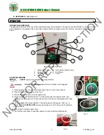
NEUTRAL/FREEWHEEL


1. 

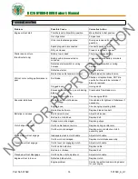
Identify the freewheel lever located in front of the right front 

wheel when viewing from operator’s station.   

2. 

Pull lever to initiate freewheel motion. 


3. 

Push lever in to initiate driver enabled motion. 


*****TIPS*****


The best performance is achieved when cutting in dry conditions. The quality of the cut is directly related to ground speed during 

cutting. Under most conditions cutting should be done at a slower ground speed. Fast speeds should be reserved for conditions 

where weeds and brush are thinned out or not very tall. If the quality of the cut is not satisfactory, attempt at slower speeds. 


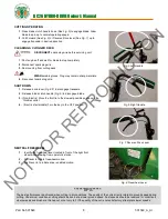
Fig. 5 

Left Handle 

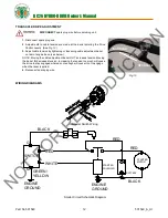
Fig. 6 

Right Handle 

CUTTING


OPERATION 


1.

 Press blade clutch handle down (See 

Fig. 5

) to engage blade. Allow 

blade to spin up to normal operating speed. 

2.

 Pull Forward (See 

Fig. 6

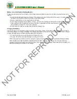
) or Reverse Drive lever (See 

Fig. 7

) up to 

engage transaxle in desired direction. 


CLEARING


A


CLOGGED


DECK


 DISCONNECT 

spark plug wire before servicing unit. 

1.

 Shut engine off and wait for blade to stop completely. 

2.

 Disconnect spark plug wire. 

3.

 Remove clog from cutting deck. 

WEAR

 durable gloves. Clog may contain sharp materials.  

4.

  Reconnect spark plug wire. 


SHUT DOWN


1.

  Release drive lever (

Fig. 6/7

) to disengage transaxle. 

2.

  Release blade clutch handle (

Fig. 5

) to disengage blade. 

3.

  (Non-Electric) Move the throttle to the slowest possible position on the 

throttle control. 

4.

   (Electric start models) Turn the key to the OFF position

.


Fig. 8 

Freewheel Lever 

Fig. 7

 Reverse Drive Lever 

NOT 

FOR 

REPRODUCTION

Содержание Hydro-Drive BC2601

Страница 1: ...o 501549 1 501549_A_HI BC2601 Hydro Drive Series Brush Cutter California Owner s Manual Beginning Serial 100515001 Original Instructions IMPORTANT READ CAREFULLY BEFORE USE AND KEEP FOR FUTURE REFEREN...

Страница 2: ...ASSEMBLY INSTRUCTIONS 5 6 OPERATION 7 8 MAINTENANCE 9 13 TROUBLESHOOTING 14 ILLUSTRATED PARTS LIST 15 23 Go to http www billygoat com for French Canadian translations of the product manuals Visitez h...

Страница 3: ...m 31 in 0 78 m 48 in 1 21 m Overall Width Overall Height Maximum Operating Slope 20 o SAFETY WARNING This product can expose you to chemicals including gasoline engine exhaust which is known to the S...

Страница 4: ...s from the Illustrated Parts List and part numbers are provided for convenience in ordering replacement labels The correct position for each label may be determined by referring to the Figure and Item...

Страница 5: ...BC26 HYDRO DRIVE Owner s Manual Part No 501549 5 501549_A_HI Brush Cutter Assembly Drawing N O T F O R R E P R O D U C T I O N...

Страница 6: ...g the hardware items 83 and 84 Tighten securely and make sure the cable isn t binding FOR ELECTRIC START MODELS Attach the throttle to the bracket then remove the starter switch item 144 from the part...

Страница 7: ...ne DO NOT START equipment with drive or blade clutch engaged Fig 1 1 Place equipment on a level firm surface that is free of rocks or other debris 2 Place throttle in fast position See Fig 1 3 Pull ch...

Страница 8: ...t Handle Fig 6 Right Handle CUTTING OPERATION 1 Press blade clutch handle down See Fig 5 to engage blade Allow blade to spin up to normal operating speed 2 Pull Forward See Fig 6 or Reverse Drive leve...

Страница 9: ...ured through the port covered by the black cap Approx 2 2 liters of oil will be needed to reach this level This is dependent on the amount of residual oil remaining in case after draining Draining of...

Страница 10: ...tem 29 and remove the cover 3 Examine condition of belt and amount of tension on belt 4 If the idler is not providing enough tension inspect the spring item 50 attaching it to the spindle base If not...

Страница 11: ...nsaxle and make sure that it does not bend over the fan blades on the transaxle Fig 10 1 Disconnect spark plug wire 2 Lift and support rear of unit to allow access to underside UNIT IS HEAVY Make sure...

Страница 12: ...CH 1 Disconnect spark plug wire 2 Adjustments to cable tension are made at the barrel entering the Drive Control Levers See Fig 13 3 Adjust cable tension by tightening or loosening cable adjustment ba...

Страница 13: ...eter Do not continue to crank your engine when the battery charge is low Charging the Battery Operate the engine for at least 45 minutes to maintain proper battery charge If the battery loses its char...

Страница 14: ...k Excessive debris built up on or blocking blade Clear debris from blade area Engine RPM set too low Check engine RPM Abnormal vibrations Blade loose or out of balance Check blade for tightness Rebala...

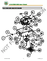
Страница 15: ...HYDRO DRIVE Owner s Manual Part No 501549 15 501549_A_HI BC26 HYDRO DRIVE DECK PARTS DRAWING Note Item No 169 includes Item No 44 Item No 20 Billy Goat Part No 501101 N O T F O R R E P R O D U C T I...

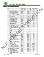
Страница 16: ...CLE 430303 1 430303 1 430303 1 29 COVER BELT DECK WA BC26 W LABEL 501602 1 501602 1 501602 1 30 PIN COTTER 1 8 X 1 8197031 1 8197031 1 8197031 1 31 WASHER 765 ID X 1 25 OD X 06 THK 850238 1 850238 1 8...

Страница 17: ...BC26 HYDRO DRIVE Owner s Manual Part No 501549 17 501549_A_HI BC26 HYDRO DRIVE ENGINE PARTS DRAWING N O T F O R R E P R O D U C T I O N...

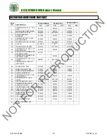
Страница 18: ...A PULL GXV390UT1 DABG 501358 1 501358 1 59 SCREWCAP 5 16 18 X 1 3 4 HCS ZP 8041031 2 8041031 2 8041031 2 SCREWCAP 1 4 28 X 1 2 HCS GR5 ZP 60 WASHER 5 16 FLAT 8171003 4 8171003 4 8171003 4 61 LABEL WAR...

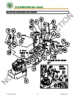
Страница 19: ...BC26 HYDRO DRIVE Owner s Manual Part No 501549 19 501549_A_HI BC26 HYDRO DRIVE HANDLE PARTS DRAWING N O T F O R R E P R O D U C T I O N...

Страница 20: ...2 830514 2 85 LABEL DRIVE DIRECTION 501502 1 501502 1 501502 1 86 PLUG TUBE INSERT 1 25 OD 791056 4 791056 4 791056 4 87 GRIP HANDLE 500267 2 500267 2 500267 2 88 GUARD HAND BC26 501215 2 501215 2 501...

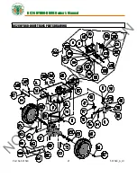
Страница 21: ...BC26 HYDRO DRIVE Owner s Manual Part No 501549 21 501549_A_HI BC26 HYDRO DRIVE TRANS PARTS DRAWING N O T F O R R E P R O D U C T I O N...

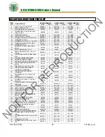
Страница 22: ...1 125 OD 351257 2 351257 2 351257 2 102 SPACER STEPPED SPEED CONTROL HYDRO DR 351347 2 351347 2 351347 2 103 SPACER EYELET SPEED CONTROL 351348 2 351348 2 351348 2 104 BUSHING 3 8 ID 1 2 OD X 3 8 LON...

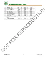
Страница 23: ...51271 S 1 139 LABEL DRIVE RELEASE 501504 1 501504 1 501504 1 140 LABEL CHOCK WHEELS 500168 2 500168 2 500168 2 158 SPRING IDLER BC 501261 1 501261 1 501261 1 161 SPRING PIN CONTROL ROD 501262 1 501262...

Отзывы: