background image

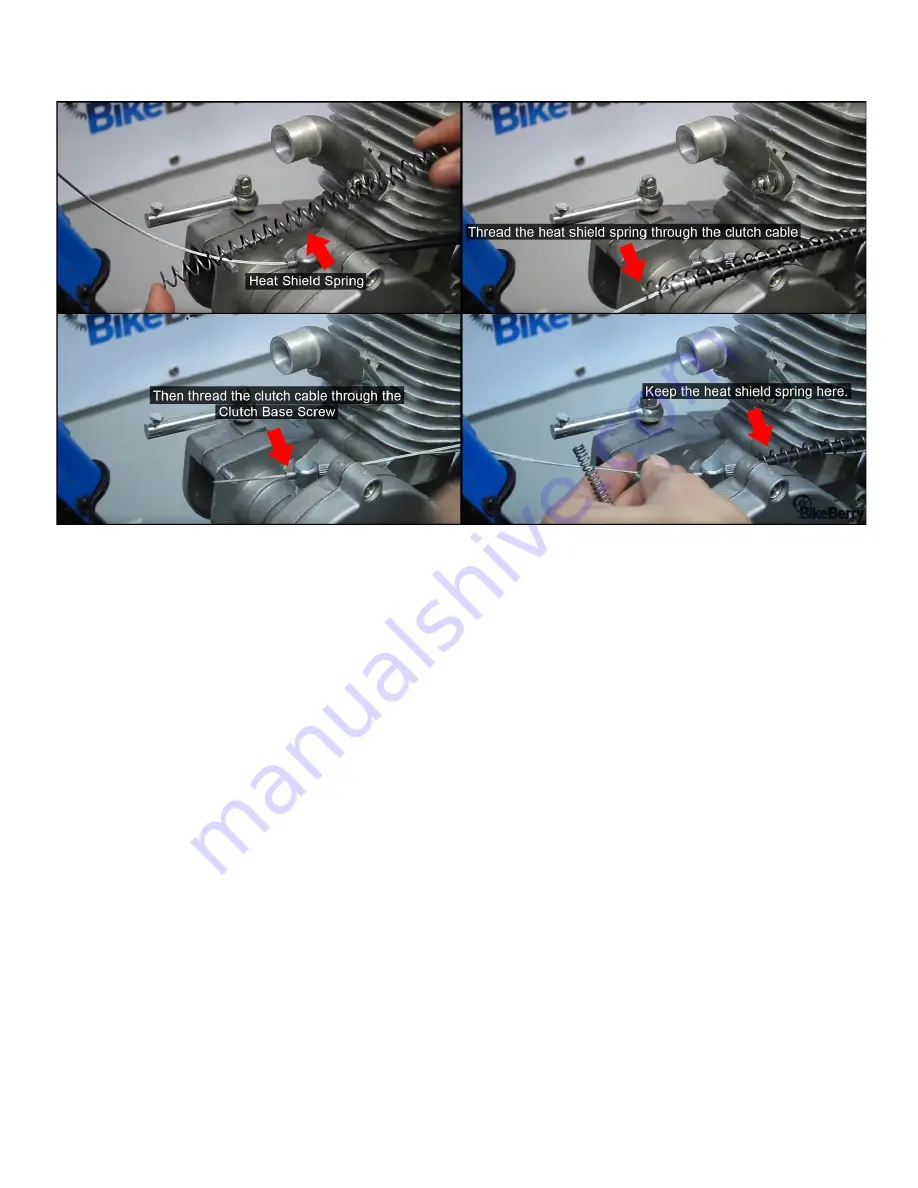
3. Thread the heat shield spring on the opposite side of the clutch cable. 
4. Thread the wire itself through the clutch base screw located right under the intake manifold. 


5. Once it’s threaded through the clutch base screw, thread the extension spring through the clutch cable. 
6. Lastly, thread the clutch cable through the clutch arm on the engine. Make sure you unthread the screw 

that will hold the clutch cable in place. 

7. Once you threaded the cable through the clutch arm, make sure you pull on the clutch cable for a 

stronger tension, while you re­thread the clutch screw into the clutch arm. 

8. Operate the clutch lever to make sure your clutch arm swings towards the motor. The key for proper 

installation is making sure the clutch arm is flush with the engine. Once you pull the clutch lever, the 
clutch arm should move inward towards the motor allowing it to disengage  your motor. Once your 
engine is disengaged, you can pedal freely. With the clutch lever in released, it will engage the motor. 

Pulling in the clutch lever will have some resistance. This is normal. 

BikeBerry.com 

1­800­317­0479 

21 

Содержание FH-BEK48

Страница 1: ...est Quality Bicycles and Engine Kits Installation and Operating Guide Model Numbers FH MEK80 FH BEK80 FH MEK80 B FH BEK80 B FH BEK48 FH MEK48 FH BEK48 B FH MEK48 B PLEASE READ THIS ENTIRE GUIDE BEFORE BEGINNING ...

Страница 2: ...n entirely at reader s own risk Furthermore Author shall not be liable for any loss of profits contracts opportunities or any direct indirect consequential loss of any kind including death and or injury or loss of property arising out of or in connection with the use of information herein News items opinions and or statements posed by Author may be unsubstantiated and should be considered as such ...

Страница 3: ...ven though the engine kit is made to be as universal as possible you bike should have these key features to ensure easier installation Your bike needs to be a standard men s beach cruiser road bike or hardtail mountain bike The seat and down tube diameter should be 25 28mm 1 1 10in with an open V Style frame The kit should fit most 26 x 1 75in rear wheel with either 12 or 14 gauge 36 count spokes ...

Страница 4: ...If your bike matches these specifications then you re ready to go BikeBerry com 1 800 317 0479 3 ...

Страница 5: ... Grip Assembly 8 Killswitch 9 Clutch Lever 10 Chain Idler Pulley 11 415 HD Drive Chain 12 Spark Plug 13 CDI 14 1 5 or 2 5L Gas Tank 15 Fuel Line 16 Fuel Valve Petcock 17 Sprocket Clamp Assembly 18 44T Drive Sprocket 19 Heat Shield Spring 20 Extension Clutch Spring 21 Spark Plug Removal Tool BONUS Universal U Mount BikeBerry com 1 800 317 0479 4 ...

Страница 6: ...brake arm If your bike has a rear coaster brake arm attached to the rear wheel remove it to install the rear sprocket Make sure not to accidently disassemble the entire rear hub doing so Once you remove the coaster brake remove the dust cover Step 2 Cut a slit in one of the rubber grommets BikeBerry com 1 800 317 0479 5 ...

Страница 7: ...n both grommets together so the 9 holes match up evenly Step 4 Align the assembly This step is the longer and most time consuming portion of the installation Place the second rubber grommet on top of the 44 tooth rear sprocket It doesn t matter which way the 44T sprocket is facing Then start pushing all 9 bolts through the assembly Line up the assembly with the rubber grommet inside the hub and th...

Страница 8: ...kes The key is to torque down each bolt in a STAR pattern to keep the the sprocket alignment true Think of tightening each bolt down in phases making sure each bolt is torqued down evenly As you tighten up your bolts each time keep watch of your center sprocket Make sure it still stays centered throughout this process or else risk having to untighten and retighten bolts to keep your sprocket cente...

Страница 9: ... caliper brakes Unfortunately there are some rear wheels that are not compatible with this sprocket adapter assembly Our best recommendation is using a BBR Tuning rear sprocket adapter for ease of installation and better coaster brake clearance Alternatively you can bend a 90 degree angle into your coaster brake arm to provide clearance Ultimately more stopping power is highly recommended Getting ...

Страница 10: ...nning the wheel and then tightening the sprocket where needed in order to get correct alignment Make sure bolts are tight Notice the concavity or indentation of teeth of the rear sprocket is inward towards spokes This helps keep the chain closer to the inside of the wheel and spokes and allows for better clearance of the rear stays of the bicycle frame BikeBerry com 1 800 317 0479 9 ...

Страница 11: ... will more than likely be the easiest fit for a Flying Horse or Mega Motors engine kit Old style beach cruisers have the same size diameter top tube down tube and seat tube Another reason why old style beach cruisers are the easiest to install a motor on is because the pedal cranks are centered below the seat post You ll know why this is important in a minute BikeBerry com 1 800 317 0479 10 ...

Страница 12: ...style bicycle with the following Only a larger down tube please go to page 12 Combination of both larger down tube and pedaling cranks please go to page 15 Mounting an Engine on Older Style Frames 1 Remove rear and front engine mount hardware from the engine block 2 Align the engine block on your frame 3 Make sure the engine is angled where the tip of the intake manifold sits parallel with the gro...

Страница 13: ... flush with the bicycle frame When installing the hardware put in the washers first then the lock washer and then thread the nut Mounting an Engine with a Larger Down Tube 1 Requires Universal Mounting Bracket 2 Disassemble the Universal Mounting U Mount BikeBerry com 1 800 317 0479 12 ...

Страница 14: ...t mounting studs from engine block You can use 1 of the 2 following techniques to accomplish this a Use a vicegrip to remove the front mounting studs b Thread 2 nuts on both front mounting studs and torque the jam nut to loosen the the mounting stud BikeBerry com 1 800 317 0479 13 ...

Страница 15: ...he manifold intake is parallel with the ground This is important for proper fuel consumption If it s angled you ll have problems feeding your motor air and fuel 9 Install the rear mount hardware but only hand tight for now We are now going to adjust the front mount 10 Install U Bracket and thread washer and nuts tight a Option use lock tight to secure nuts 11 Install rear motor mount hardware to c...

Страница 16: ...ngine with Forward Pedaling Cranks Larger Down Tube 1 Requires JNM Vibration Motor Mount Heavy Duty Universal U Mount 2 Remove all mounting hardware from front and rear mounting studs BikeBerry com 1 800 317 0479 15 ...

Страница 17: ...You can use 1 of the 2 following techniques to accomplish this a Use vicegrip to remove the front and rear mounting studs b Thread 2 nuts on both front and rear mounting studs and torque the jam nut to loosen the mounting stud BikeBerry com 1 800 317 0479 16 ...

Страница 18: ...nt and rear studs from the JNM Vibration Motor Mount assembly a option Use Locktite to secure studs inside engine block 5 Then thread the rear mounting bracket and both front and rear rubber mount BikeBerry com 1 800 317 0479 17 ...

Страница 19: ... plate and thread the top hole pattern through the front motor mount 8 Place 1 of the 2 U brackets on the bottom hold patterns over the larger down tube 9 Thread the washer locking washer and nuts for the front mount 10 Thread the remaining rear mount assembly for the rear mounting studs BikeBerry com 1 800 317 0479 18 ...

Страница 20: ...alling the Clutch Assembly Tool Required Open Wrench Screwdriver or Allen Keys Wrench Required parts clutch cable clutch lever the heat shield spring and the extension spring BikeBerry com 1 800 317 0479 19 ...

Страница 21: ...ch lever on the left side of your handlebar 2 The clutch cable has 2 different looking ends Take the side with the nipple piece and install the clutch cable into the clutch lever by threading the nipple piece into the clutch lever nipple housing BikeBerry com 1 800 317 0479 20 ...

Страница 22: ...ble through the clutch arm make sure you pull on the clutch cable for a stronger tension while you re thread the clutch screw into the clutch arm 8 Operate the clutch lever to make sure your clutch arm swings towards the motor The key for proper installation is making sure the clutch arm is flush with the engine Once you pull the clutch lever the clutch arm should move inward towards the motor all...

Страница 23: ...BikeBerry com 1 800 317 0479 22 ...

Страница 24: ...remove the flower nut a The easiest way to remove the flower nut is pulling in the clutch lever and disengage the motor Then press the clutch plate against the engine to free the flower nut to unthread easily 3 Then remove the clutch plate You ll notice that if you spin the 3 pegs sticking out in the middle of the gear it will also spin the 10T sprocket BikeBerry com 1 800 317 0479 23 ...

Страница 25: ...6 Install the chain on both front and rear sprocket 7 Measure and remove any excess chain for a tight fit We recommend less than a inch in play Remove any slack with a motorized bike chain breaker 8 Reinstall the master link 9 Reinstall the gear case assembly and cover Then reinstall the clutch case cover BikeBerry com 1 800 317 0479 24 ...

Страница 26: ...st it c While you re adjusting the idler pulley keep 2 things in mind make sure the chain is tight only providing no more than inch of slack and make sure the chain is aligned straight for proper chain guidance d Once you have those 2 things checked thread the nuts as tight as possible Use 2 mm wrenches for each side While tightening the idler pulley it will move side to side and off position so w...

Страница 27: ...BikeBerry com 1 800 317 0479 26 ...

Страница 28: ...t done so already 2 Take your measuring tape and measure 4 inches from the end of the right side of the handlebar 3 Mark that position with a permanent marker right at the top of the handlebar 4 Drill a 1mm pilot hole where you marked your handlebar Then follow it up with a 5mm drill 5 Thread the throttle cable through the kill switch Then thread the L piece on the kill switch 6 Then thread the ca...

Страница 29: ...hing together You can adjust the L piece so it sits more comfortably with the locking nut NOTE Care should be taken with the cable and throttle grip handle If you are too rough with it you will break it Be gentle when installing the throttle 8 Optional Install the other handle grip on the left side of the handlebar BikeBerry com 1 800 317 0479 28 ...

Страница 30: ...stalling the Carburetor The other end of the throttle cable is installed inside the carburetor 1 NT Carburetor 2 Screw Top 3 Spring 4 Slide 5 E Washer 6 Jet Needle 7 C Clip BikeBerry com 1 800 317 0479 29 ...

Страница 31: ... e clip attached 2 Once removed reassemble these pieces outside of the carburetor a Thread the jet needle through the slide b Then drop and align the the C washer over the jet needle Make sure the slit on the C washer is aligned with the slit on the slide c Then place the spring and then the screw top over the slide BikeBerry com 1 800 317 0479 30 ...

Страница 32: ... through the slit and drop the cable s nipple piece into the slide housing 5 Once you let go of the spring the whole assembly should be held in place 6 Reinstall the assembly back into the carburetor Make sure you line up the slide slit with the guide peg inside the carburetor Then screw everything back on tightly 7 Loosen the manifold clamp and install the carburetor on the intake manifold BikeBe...

Страница 33: ... and the magneto loops set is installed inside the engine NOTE When it comes to wiring you may need to splice your wires together which involves cutting and stripping the insulation away from the tip of the wires 1 Remove the spark plug crown before attaching the CDI spark plug cap WARNING Fail to remove this crown can damage or ruin the spark plug cap 2 Once you mount your CDI install the CDI spa...

Страница 34: ... Connect the blue wire from the CDI to the blue wire from the magneto 5 Connect the green wire sometimes black from the kill switch to the black wire from the CDI 6 Connect the red and yellow from the kill switch to the blue wires from the CDI BikeBerry com 1 800 317 0479 33 ...

Страница 35: ...your CDI spark plug cap is installed remove it before removing the spark plug b Engage the motor by releasing the clutch c Hold the spark plug against the engine head to ensure visible spark d Then hold the rear wheel off the ground and rotate it to create spark e If you have spark you installed it properly f If you do not have spark please check your wiring BikeBerry com 1 800 317 0479 34 ...

Страница 36: ...Installing the Muffler Exhaust Gas Tank Fuel Assembly Once you have all the major components completed install the remaining parts BikeBerry com 1 800 317 0479 35 ...

Страница 37: ...include the clutch spring If your model does not it s normal 2 Stroke engine kits do not require it 5 Make sure the bevel wheel is spinning freely If it is you ll be able to move it with your hand If it does not tap the 3 studs counter clockwise gently with a rubber mallet Repeat until clutch bevel wheel spins freely 6 Assemble the spring and clutch plate the way it was when you started and tighte...

Страница 38: ... your carburetor manifold is well sealed and the intake manifold nuts are tight Now for the NT Carburetor adjustment There s only 1 direct method in turning these carburetors Adjust the E Clip connected to your jet needle It has a series of notches at the top that represents different fuel mixtures You can remove and reposition the E clip for any desired position The top notch is for the leanest m...

Страница 39: ...n Bearing 16 Adjustment Nut 17 Main Clutch Spring 18 Clutch Pin Mandrel 19 Flat Key 20 Clutch Shaft 21 Pintle 22 Ferrule 23 10 Tooth Sprocket 24 Clutch Actuator Bearing 25 Shaft Fixed Pin 26 Bucking Bar 27 Clutch Camshaft 28 Clutch Arm 29 Washer 30 Nylon Lock Nut 33 Extension Spring 35 Clutch Screw Base Pt 1 36 Clutch Screw Base Pt 2 37 Heat Shield Spring 38 Clutch Cable 39 Clutch Lever 40 Clutch ...

Страница 40: ... Motor Mount 11 Motor Mount Bracket 12 Rear Mount Washer 13 Rear Mount Nylon Lock Nut 14 Motor Mount Stud 15 Bottom Crank Case Body 16 Front Motor Mount Stud 17 Keyway 18 202 Main Bearing 19 Crank 20 Crank Bearing 21 Crank Connecting Pin 22 Crank Cover 23 Crank Arm 24 Piston Ring Sets 25 66 80cc Piston 26 Piston Retaining Clips 27 Piston Pin 28 Crank Connector Bearing BikeBerry com 1 800 317 0479 ...

Страница 41: ...der Body Cap 3 66 80cc Top Head Gasket 4 Motor Head Stud 5 66 80cc Cylinder Body 6 Intake Manifold Gasket 7 66 80cc Bottom Head Gasket 8 Intake Exhaust Stud 9 Muffler Exhaust Gasket 10 Locking Nut 11 Washer 12 Lock Washer BikeBerry com 1 800 317 0479 40 ...

Страница 42: ... Assembly Plate 1 of 2 3 Sprocket Assembly Plate 2 of 2 4 9 Hole Sprocket Assembly Grommet 5 9 Hole Sprocket Assembly Grommet 6 Nylon Lock Nut 7 Lock Washer 8 Washer 11 44T Rear Sprocket 12 HD 415 Drive Chain 13 Chain Guard BikeBerry com 1 800 317 0479 41 ...

Страница 43: ...iagram 40 Magneto Case Cover Screw 43 Magneto Case Cover Gasket 47 Magneto Loop Set 48 Magneto Washer 50 Magneto Nut 51 Magneto 54 Clutch Case Cover Screw 55 Clutch Case Cover 56 CDI 57 Spark Plug Cap BikeBerry com 1 800 317 0479 42 ...

Страница 44: ... Washer 8 Nylon Lock Nut 9 C Clip 10 Throttle Cable 11 Cable Adjustment 12 Carburetor Spring 13 Float Bowl Screw 14 Washer 15 E Washer 22 Jet Needle 25 Fuel Intake Nozzle 32 Intake Manifold 34 Air Filter Cap 35 Air Filter 43 Jet 44 NT Carburetor 45 Float Bowl Gasket 46 Float 50 Float Bowl BikeBerry com 1 800 317 0479 43 ...

Отзывы: