Страница 1: ...rvice Manual Installer Please take the time to read and understand these instructions prior to any installation Installer must give a copy of this manual to the owner Owner Keep this manual in a safe...
Страница 2: ...uilding 7 Immediately call your local gas supplier after leaving the building Follow the gas supplier s instructions 8 If you cannot reach your gas supplier call the Fire Department Fire Hazard Keep a...
Страница 3: ...ARDS AND APPLICABLE CODES 8 SECTION 5 MAJOR COMPONENTS 9 SECTION 6 HEATER INSTALLATION 12 SECTION 7 OPTIONAL HEATER ACCESSORIES 29 SECTION 8 VENTING 33 SECTION 9 GAS PIPING 43 SECTION 10 WIRING 45 SEC...
Страница 4: ......
Страница 5: ...hin sheet metal parts have sharp edges To prevent injury the use of work gloves is recommended The use of gloves will also prevent the transfer of body oils from the hands to the surface of the reflec...
Страница 6: ...Each burner will have a unique 14 digit serial number used for identification purposes to allow the lookup of various items such as manufacture test records replacement part identification and manufa...
Страница 7: ...ocate your the model number and install configuration located on the burner and noted in this manual On the tag write the proper clearance dimensions in permanent ink according to your model number an...
Страница 8: ...adjacent materials are protected from degradation Maintain clearances from heat sensitive equipment and workstations Maintain clearances from vehicles parked below the heater Maintain clearances from...
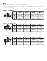
Страница 9: ...B 9 23 cm 9 23 cm 9 23 cm 18 46 cm C 69 176 cm 82 209 cm 85 216 cm 102 260 cm D 54 138 cm 65 166 cm 69 176 cm 73 186 cm FIGURE 2 Level Reflector IRH 80 IRH 125 IRH 150 IRH 200 A 6 16 cm 6 16 cm 6 16...
Страница 10: ...cm B 8 21 cm 8 21 cm 8 21 cm 10 26 cm C 65 166 cm 77 196 cm 83 211 cm 85 216 cm D 60 153 cm 69 176 cm 74 188 cm 79 201 cm FIGURE 6 U Tube Standard Reflector IRH 80 IRH 125 IRH 150 IRH 200 A 6 16 cm 6...
Страница 11: ...tube connect Unvented Vented Radiant Tubes Vent Pipes FIGURE 8 U Tube Opposite 45 Reflector IRH 80 IRH 125 IRH 150 IRH 200 A 8 21 cm 10 26 cm 12 31 cm 12 31 cm B 60 153 cm 70 178 cm 74 188 cm 76 194...
Страница 12: ...shall be made to assure accessibility to suspended heaters for recurrent maintenance purposes 4 3 Public Garages Installation in garages must be in accordance with the following codes United States R...
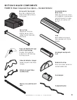
Страница 13: ...r Hanger with Clamp Package Position this hanger no more than 4 10 cm away from the burner Flex Gas Line with Shut off Cock Reflector Support Strap and Wire Form Tube and Reflector Hanger Suspend syst...
Страница 14: ...er Head for Outside Air Collar 3 3 3 3 92311800 Lock Nuts 10 32 4 4 4 4 03051501 Turbulator Adapter 1 03051502 Turbulator 2 5 ft 76 cm Aluminized Steel 4 03051509K Swirler Package 10 ft 3 m Contains Q...
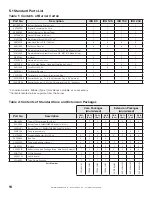
Страница 15: ...LL RIGHTS RESERVED 11 Table 3 Component Package Guide Standard Reflector Model Tubing Length Aluminized Core Packages IRH 80 20 ft 6 m CP20ALUM IRH 125 30 ft 9 m CP30ALUM IRH 150 40 ft 12 m CP40ALUM I...
Страница 16: ...with these instructions The gas or the electrical supply lines must not be used to support the heater Do not locate the gas or electric supply lines directly over the path of the flue products from t...
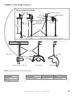
Страница 17: ...pical Suspension Details Beam Clamp Concrete Beam Wood Beam Locknut Anchor Screw Hook 3 8 Rod 3 8 X Chain Size 3 16 Minimum S hooks 24 min 61 cm Turnbuckle not included Allows for thermal expansion of...
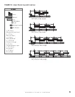
Страница 18: ...LLC ALL RIGHTS RESERVED 14 FIGURE 12 Linear Heater Assembly Overview Reflector End Cap Burner Tube Clamp Package Burner Tube Tube and Reflector Hanger Coupling Reflector Support Reflector Tube Turbula...
Страница 19: ...nger Coupling Assembly Vent Adapter a 14 36 cm Reflector width not shown b 2 5 cm End cap to burner c 2 5 cm End cap to hanger d 7 6 2 3 m Distance first hanger e 10 3 m Distance between hangers f 12...
Страница 20: ...e Installation Note Tubing requires a downward slope of 1 2 13 mm per 20 ft 6 m away from burner Description Burner Tube S Hook Tube Reflector Hanger Offset mounting hole must be to the top S Hook Han...
Страница 21: ...WWW BIGASSFANS COM 2021 DELTA T LLC ALL RIGHTS RESERVED 17 Step 6 2 Tube Clamp Package Installation Description Tube Clamp Package Bolt Tube Clamp Flat Washer Nut Torque 120 in lb 13 56 N m...
Страница 22: ...erneath guide rail Insert wide end of slide bar coupling lock into guide rail on opposite end of tabs Slide the slide bar coupling lock up the guide rail until snug approximately 3 8 cm to 4 10 cm Ins...
Страница 23: ...20 ft 6 m IRH 125 30 ft 9 m IRH 150 40 ft 12 m IRH 200 50 ft 15 m Step 6 3 1 Coupling and Tube Assembly Tighten slide bar as shown below Be sure not to over tighten slide bar coupling lock Slide bar...
Страница 24: ...n chart below Turbulator Installation Model Tube Section IRH 80 2nd 10 ft 3 m Section Description Turbulator Adapter 2 5 ft 76 2 cm Turbulator Section 2 ft 61 cm Tube Twist Turbulator Section Turbulat...
Страница 25: ...sections For this reason 15 ft and 20 ft long swirler packages each contain two swirler starter sections to allow for starter pieces to be installed before and after U sections Swirler starter section...
Страница 26: ...s model must be complete prior to coupling installation for proper swirler starter tab placement Fold swirler tab over tube as shown Internal Coupling Pin Coupling Tab Burner Tube Tube and Reflector H...
Страница 27: ...Starter Section 10 ft 3 m Tube Pivot Point Swirler Adapter Section Swirler Adapter Section Pivot Point Swirler Adapter Section Swirler Starter Section Swirler Adapter Section 10 ft 3 m Tube Burner Tu...
Страница 28: ...10 ft 3 m Pivot Point Swirler Adapter Section Burner Tube Coupling Swirler Starter Section Tab Swirler Adapter Section Swirler Starter Section Vent Adapter Tab Vent Adapter Swirler Starter Section Swi...
Страница 29: ...3 m Burner Tube Coupling Swirler Adapter Section Pivot Point Swirler Starter Section Tab Swirler Adapter Section Swirler Starter Section Vent Adapter Tab Vent Adapter Swirler Starter Section Pivot Poi...
Страница 30: ...r with reflector hanger and support strap Reflector must not touch tube Failure to follow these instructions can result in death injury or property damage Note All tube surfaces must be covered by a r...
Страница 31: ...t the first and second reflector is a slip overlap Thereafter every third reflector joint is a slip overlap A slip overlap is achieved by either a Both reflectors lay inside a hanger No reflector supp...
Страница 32: ...acle on rear of burner Note Do NOT face blower air inlet towards hinged access panel if connecting fresh air inlet Doing so will interfere with access panel Description Bolt Lock Washer Blower Blower...
Страница 33: ...n either a standard horizontal position a 45 position or in an opposite 45 position as shown on page 6 When using a U tube configuration the following additional rules must be adhered to A minimum of...
Страница 34: ...Support Burner Vent Adapter Tube Clamp Package Turbulator Swirler Tube Burner Tube Couplings Reflector Reflector End Caps U Clips U Tube U Tube Standard Tight U Bolt 4 in 10 cm U bolt secured to burn...
Страница 35: ...r e 10 3 m Distance between hangers f 5 1 5 m Distance between last full tube hanger and half tube hanger g 12 5 32 cm Burner length h 11 28 cm Burner height Requires the last reflector before the U t...
Страница 36: ...2 per reflector Use additional supports in high air movement applications Description Reflector Side Extension Package Reflector Side Extension 96 244 cm Retainer Clips Sheet Metal Screws Order Separ...
Страница 37: ...all must have an approved thimble to conform with the above listed codes Vent pipe must be sloped downward away from the heater 1 2 in 1 cm for every 20 ft 6 m The heater may be individually vented or...
Страница 38: ...3 Horizontal Venting Category III All horizontal venting configurations for this product are considered Category lll In noncombustible walls only vent terminal may be used For 4 in 10 cm vents in eit...
Страница 39: ...or both Vertical and Horizontal IRH 80 III III III IRH 125 III III III IRH 150 III III III IRH 200 III III III For common vertical venting of more than two heaters see 8 14 Common Vertical Venting Cat...
Страница 40: ...will form in the vent pipe Insulation and additional sealing measures high temperature silicone at all seams are required Optional heat exchanger beyond minimum lengths is considered as vent length f...
Страница 41: ...e A continuous section of type B vent may only be used to pass through the roof or outside of the building Vertical venting Category III does not allow the use of type B vent inside of the space SIDE...
Страница 42: ...d VH1 6 or Equivalent Vent Adapter 4 10 cm Single Wall Pipe 4 10 cm Single Wall Pipe Vent Adapter Sweeping Y Connection by others 6 15 cm Single Wall Pipe Outside Wall Description Vent Terminal 6 in 1...
Страница 43: ...e Wall Pipe D D Area must equal sum of open area of individual vents 4 10 cm Single Wall Pipe Vent Adapter TOP VIEW Requirements Maximum of four heaters can be commonly vented through the roof Heaters...
Страница 44: ...ted heaters The air supply duct may have to be insulated to prevent condensation on the outer surface The outside air terminal must not be more than 1 ft 31 cm above the vent termination while maintai...
Страница 45: ...escription Vent Cap Metalbestos 4 in 10 cm 8 15 4 Vertical Outside Air Supply for Double Heater Installation Vent Cap Roof Burner Burner Sweeping T Connection by others 6 15 cm Single Wall Pipe Flex H...
Страница 46: ...llation 4 10 cm Single Wall Pipe seal all joints Sweeping Y Connection by others Flex Hose Recommended 6 15 cm Single Wall Pipe Vent Cap Burner Burner Band Clamp Recommended Outside Wall Description V...
Страница 47: ...pleted There is an expansion of the tube with each firing cycle this will cause the burner to move with respect to the gas hose This can cause a gas leak resulting in an unsafe condition if the gas co...
Страница 48: ...n left 45 45 Pipe Nipple Burner Assembly shown without blower assembly Heater Movement 90 Pipe Elbow not included Flexible Gas Hose 36 91 cm length 12 30 cm 3 8 cm max displacement Alternate positions...
Страница 49: ...heaters controlled by a line voltage thermostat For heaters on a low voltage thermostat see 10 2 Low Voltage Thermostat Wiring on page 46 Heaters must be grounded in accordance with applicable codes U...
Страница 50: ...ermostat Wiring FRONT VIEW BACK VIEW DPDT TRANSFORMER RELAY BLACK BLACK WHITE RED 120 V 60 HZ SUPPLY CIRCUIT L N GND N L N L GND GND BURNER 1 BURNER 2 MAXIMUM 8 BURNERS PER RELAY ADDITIONAL BURNERS De...
Страница 51: ...T LLC ALL RIGHTS RESERVED 47 10 3 Internal Wiring IGNITION MODULE 19 16 18 IGNITER PRESSURE SWITCH BLUE 1 3 BLUE BLACK YELLOW BROWN GAS VALVE GREEN YELLOW YELLOW GREEN BLACK WHITE TRANSFORMER 1 3 5 4...
Страница 52: ...ELECTRODE GROUND POWER SENSE SPARK VALVE IGNITION MODULE GAS VALVE 10 5 Electrical Connection to the Burner Connect wires together with suitable approved wire connections Green White Black Green to Gn...
Страница 53: ...ng operation the ignition module will attempt the multiple trial sequence described in step 5 If ignition is not re established the module will lockout for one hour or until reset 7 After lockout the...
Страница 54: ...nothing is lodged underneath the reflector or in between the tubes Immediately remove objects in violation of the clearances to combustibles See SECTION 3 CLEARANCES TO COMBUSTIBLES on page 4 Reflecto...
Страница 55: ...arbon residue or erosion of the electrode The electrode gap should be 1 8 3 2 mm Thermostat There should be no exposed wire or damage to the thermostat See SECTION 10 WIRING on page 45 Suspension Poin...
Страница 56: ...mable objects liquids and vapors the minimum required clearances to combustibles away from heater Some objects will catch fire or explode when placed close to heater Explosion Hazard Turn off gas supp...
Страница 57: ...eeded Carefully reset spark gap to 1 8 Are the air hoses to the pressure switch secure and leak free Repair replace or tighten hoses as necessary Check wiring between the blower motor and transformer...
Страница 58: ...cock Contact gas company Are the wires connecting the ignition module OK Replace correct wires Replace ignition module Turn valve ON Is the knob on the gas valve in the ON position Replace gas valve D...
Страница 59: ...SERVED 55 12 2 Manifold Gas Pressure Setting 6 5 4 3 2 1 0 1 6 5 4 3 2 6 5 4 3 2 1 0 1 6 5 4 3 2 Top View of Heater Gas Flow Inlet Gas Pressure Port Manifold Gas Pressure Port Side View of Valve Natur...
Страница 60: ...e to follow these instructions can result in death electric shock injury or property damage See warnings and important information before removing or replacing parts After any maintenance or repair wo...
Страница 61: ...2021 DELTA T LLC ALL RIGHTS RESERVED 57 Blower Assembly DSI Ignition Module Blower Outlet Gasket Tube Gasket Electrode Mica Window Assembly Burner Cup Assembly REAR VIEW TOP VIEW Transformer Pressure...
Страница 62: ...e Gasket 02558501 Tube Gasket 02568200 Burner Cup Assembly 03020100 Gas Valve Natural 90032510 Gas Valve LP 90032512 Electrode 90427400 DSI Ignition Module 90439500K Transformer 90436900K Pressure Swi...
Страница 63: ...10 5 wc PIPE CONNECTION 1 2 NPT DIMENSIONS Vent Connection Size 4 10 cm Outside Air Connection Size 4 10 cm Refer to figure above for dimensional information ELECTRICAL RATING ALL MODELS 120 V 60 Hz 1...
Страница 64: ...BF170101NA Rev A 10 15 2021 2348 Innovation Drive Lexington KY 40511 1 877 BIG FANS WWW BIGASSFANS COM...