

EX200 Electro-Hydraulic Actuator Positioner
Bifold Orange Limited.
Drwg. No.: ORM0001 Issue : 1 Date : 24/06/2015 Page :
9 of 20
First time operation
WARNING!!
The actuator and associated mechanical equipment connected to it could possibly move in an unpredictable
manner during initial calibration. Ensure that all personnel take appropriate precautions.
1. Ensure that any end of travel limit switches and mechanical stops are correctly adjusted before operation.
2. Apply power and provide the 4-20mA command signal. Press the Auto/Manual Switch. Check that the Auto/Manual
LED is lit.
3. Operate the Increase and Decrease buttons and confirm that the actuator moves as required.
4. The system must be calibrated before automatic mode is selected.
Calibration
Calibration can only be carried out local to the EX200 unit so it is essential to have purged the area in order to access the
EX200 and provide local command signal injection. An alternative is to use the remote DCS to inject and read the actual
position signal and transfer the information by handheld radio. If this approach is used ensure that the radio is operated
2m or more from the EX200 and associated wiring.
A command signal is required, normally in the range 4-20mA (Terms 20+ and 21-) and a DVM with a 0-200mA range to
read the retransmitted position signal (Terms 13+ and 14-).
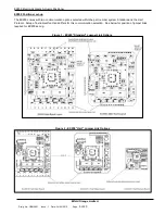
1. Press the CALIBRATE button, and hold until the CALIBRATE LED goes out. When the button is released, the
CALIBRATE LED will flash briefly once per second.
2. The positioner has been switched automatically into Manual, non-stepping mode so use the INCREASE /
DECREASE buttons to set the actuator to the required position for the minimum, 4mA command signal. This
must be the position the DEC solenoid will drive the actuator to.
3. Set the command signal to 4mA.
4. Adjust the CAL1 potentiometer to give the required output for the chosen position. Note that this not need be
4mA to match the command signal, but can be any value in the range 0.5mA to 22mA.
5. Press and hold the CALIBRATE button until the CALIBRATE LED goes out. Release the button and the
CALIBRATE LED will flash twice briefly every second.
6. Use the INCREASE and DECREASE buttons to set the actuator to the required position for the maximum, 20mA
command signal. This must be the position the INC solenoid will drive the actuator to.
7. Set the command signal to 20mA.
8. Adjust the CAL1 potentiometer to give the required output for the chosen position. Note that this not need be
20mA to match the command signal, but can be any value in the range 0.5mA to 22mA.
9. Press and hold the CALIBRATE button until the CALIBRATE LED goes out. Release the button to complete the
calibration sequence.
General operation
When calibration has been completed the EX200 reverts to automatic mode and to stepping operation if DIL switch 4 is
set ON. The actuator should now follow the command signal input and move to the desired position.
If there is any instability in positioning, particularly if the hydraulic flow rate is high, then the DEADZONE potentiometer
can be set progressively clockwise, half a turn at a time, until stable positioning following a step change can be achieved.
Normal operation - fault detection
If the command signal or the feedback signal goes towards zero (less than 0.5V at the terminals, across any shunt fitted)
then the selected fail mode will operate and the OK light will be removed. The actuator will either freeze position, drive
down or drive up and the control to the auxiliary solenoid will be removed. The system will recover to normal operation
when the signals are re-instated. If the external fault contact is broken, then the fault output will change, as will the
auxiliary solenoid if they are linked as described in Positioner Set-up. The fault condition is reset as soon as the external
fault contact is restored. If the unit is in "stepping mode" (DIL switch 4 = ON) then failure mode drive can be either in the
selected stepping mode or, if DIL switch 1 is ON, then the unit will fast-fail to its default position.
For the EX200 with the “Hart” Communication option, if the external fault contact is broken, then the fault output will
change, as will the auxiliary solenoid if the appropriate bit is set, via HART in Command 129 (81h), otherwise the fault
input operates only the fault output. The fault condition is reset as soon as the external fault contact is restored. If the
unit is in "stepping mode" (DIL switch 4 = ON) then failure mode drive can be either in the selected stepping mode or, if
DIL switch 1 is ON, then the unit will fast-fail to its default position. If remote changes are enabled then all the above
option can by changed via HART in Command 129 (81h).


