- 43 -
CoNdENSATE TRAP
21 CoNdENSATE TRAP
21.1 function
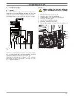
The condensate trap A in Figure 21.1 and Figure 21.2 allows
the discharge of the condensate via the condensate drain pipe
avoiding in the mean time the escape of combustion products.
A plastic ball closes the trap outlet in case that the trap is empty.
figure 21.1
A
If the drain pipe is plugged or in any case in which the conden-
sate isn’t correctly evacuated, the condensate level rises filling
the trap and reaching the condensing heat exchanger.
When the condensate reaches the lower part of the exchanger
obstructs the exhaust gas flow and the boiler stops (no signal
from the air pressure sensor).
21.2 Removal
Warning: isolate the boiler from the mains electrici-
ty supply before removing any covering or compo-
nent.
1 Remove the front and right case panels.
2 Disconnect the trap from the draining pipe.
3 Using pliers, remove the spring B moving it upwards.
4 Disconnect the rubber pipe C.
5 Unscrew the nut D and lower the trap.
6 Disconnect the wirings from the trap.
7 Reassemble carrying out the removal operations in reverse
order.
figure 21.2
A
d
b
C
Содержание Riva Plus HE M296.24SM/C
Страница 2: ......
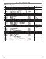
Страница 45: ...45 Short spare parts list 1 2 6 4 5 7 3 8 14 12 18 20 21 23 25 26 13 15 24 16 17 9 10 11 9 19 27 22 Figure 22 1...
Страница 46: ...46 NOTE...
Страница 47: ......


