Biasi Riva Advance Combi Скачать руководство пользователя страница 61

RIVA ADVANCE COMBI MANUAL 

6

1

17. Annual Maintenance Cont.

17.13 Water inhibitor concentration:

Where  chemical  products  are  used  the  level  of  water  treatment  should  be  checked  on  an 

annual basis and re treated after full or partial drain down.

A conductivity meter can be used to check the correct concentration of inhibitor in the heating 

water. See the section 15.1 of this handbook.

17.14 Checking the condensate drain pipe:

The condensate drain

 system should be 


checked yearly during a service.  

C

heck:

  That no solid deposits have formed, if so 

remove them.


  Remove  the  forks  E  and  remove  the 

condensate trap A moving it downwards 

(Fig. 17.8).

Figure 17.8 

A

D

E

17.16 Setting the boiler chimney sweep function:

With  the  boiler  set  in  chimney  sweep 

mode, it is possible to exclude some boiler 

automatic  functions  making  check  and 

control operations easier.

  Position the control panel knobs as shown 

in Figure 17.9.

Figure 17.9 

8

7

6


Electrically power the boiler, the following 

will appear on the LCD display.

Figure 17.10 

  To  enter  Chimney  cleaning  mode,  enter 

programming  by  pressing  the  reset 

button  6  in  Figure  17.9  for  15  seconds 


That  the  condensate  drain  piping  is  not 

clogged

, if so clear the clog.

Unscrew the plug D to clean inside the pipe.

Removal

17.15 Checking Low Water Cutoff

If a low water cutoff is installed on a system, it’s function should be checked as part of 

the yearly service.  Refer to the low water cutoff manufacturers instructions 

f

or 

maintenance and testing. 

Содержание Riva Advance Combi

Страница 1: ...itch do not use any phone in your building Immediately call your gas supplier from a neighbor s phone Follow the gas supplier s instructions If you can not reach your gas supplier call the fire depart...

Страница 2: ...fully as those we specify The installing contractor is the best judge of a system s specific requirements as well as the local availability of certain makes and models of controls and accessories The...

Страница 3: ...Flue 9 2 20 Pipe Connections 10 Gas Pipe Connections 11 Electrical Connections Wiring 3 Power Connection 12 1 3 Connection to the Electricity Supply 12 2 3 Room Thermostat Connection 12 3 3 Relay Pane...

Страница 4: ...Warnings 17 1 58 Dismantling the External Panels 17 2 58 Emptying the D H W System 17 3 58 Emptying the D H W Circuit 17 4 59 Combustion Analysis Check 17 5 59 Cleaning the Condensing Heat Exchanger a...

Страница 5: ...t be performed by a qualified installer service agency or the gas supplier WARNING If the information in this manual is not followed exactly a fire or explosion may result causing property damage pers...

Страница 6: ...en confused with those of influenza and the highest incidence of poisoning occurs at the onset of cold weather or during flu season A victim may not experience any symptoms only one symptom or a few s...

Страница 7: ...read the literature and warranties supplied by the manufacturers of the various accessory equipment This equipment is warranted by the respective manufacturers not by Quincy Hydronic Technology Inc E...

Страница 8: ...an integral frost protection system to prevent frost damage which can occur in areas susceptible to very cold weather conditions Boiler operation recognition system should the boiler not be used for l...

Страница 9: ...4500 ft MBH 112 5 Max Exhaust temperature F 190 GAS FLOW RATE Gas Min Max Natural ft h 31 0 121 0 Propane lb h 1 5 5 7 CLEARANCE TO COMBUSTIBLES Front in 18 Back in 0 Top in 10 Sides in 2 Bottom in 8...

Страница 10: ...ate trap 18 Air hose 19 Transformer 20 Air box air gas mixer 21 Air pressure switch 22 Flame detecting electrode 23 Burner 24 Condensing heat exchanger 25 Flue temperature probe NTC 26 D h w flow swit...

Страница 11: ...11 41 39 42 43 44 45 38 40 37 17 15 30 9 10 14 29 12 27 28 16 6 23 32 Note Pressure Relief Valve 1 should be piped to a drain or to the floor as close as possible to a drain Note Figure is not intende...

Страница 12: ...4 Y G BL BR BR BL W O W GY t t BK R R BK BL BL BL BL R W BL W BL R M R BK GY W R GY W BK t BR BL W BK BK W BR BL COM NO R R R R GY BK GY External controls terminal block Electric supply terminal bloc...

Страница 13: ...NO YES Is flue temperature higher than 110 C YES NO beginning of wait period End of wait period YES NO YES starts ignition discharges Opens gas valve beginning of ignition period flame presence YES in...

Страница 14: ...rpm YES cancels lock Is fan rpm exact NO YES Is flue temperature higher than 110 C YES NO beginning of wait period End of wait period YES NO starts ignition discharges Opens gas valve beginning of ign...

Страница 15: ...vers installed There should be two louvers place each within 12 of the ceiling and floor respectively Each vent will have a free area of 54 square inches 3 0 i n 2 0 in 10 0 i n 2 0 in CLOSET INST ALL...

Страница 16: ...lding 3 The vent hood shall not be less than 12 above normal snow level 4 The vent hood shall not be less than 2 feet from an adjacent building 5 The vent hood shall be not less than 7 feet above grad...

Страница 17: ...Be sure to level the bracket by adjusting the screw in the vertical slot 4 Pre drill the remaining hole in the mounting bracket and secure the final screw 5 Mark and drill the exhaust intake pipe hole...

Страница 18: ...nd determine there is no blockage or restriction leakage corrosion and other deficiencies which could cause an unsafe condition c Insofar as is practical close all building doors and windows and all d...

Страница 19: ...strict compliance with the manufacturer s instructions A copy of the installation instructions shall remain with the appliance or equipment at the completion of the installation 4 A metal or plastic i...

Страница 20: ...st intake outside PART RI 9990387 Figure 9 1 Coaxial 2 4 4 0 inches nominal length 3 3 ft It can be mounted to allow discharge to the rear or either side of the boiler via the flanged boiler adapter e...

Страница 21: ...nly be used to discharge horizontally it is not designed to enable termination in the vertically Installation Drill a hole 4 5 in diameter through the outside wall that is less than 18 thick Cut the p...

Страница 22: ...to finish the piping using CPVC or Polypropylene Canadian Installations as a system and must be installed as such Different manufacturers have different materials different BH Vent manufacturers this...

Страница 23: ...ar C from the adapter kit to the top of the boiler using the supplied screws Insert the boiler adapter B into the collar Check that the exhaust gasket D is installed on the outlet of the boiler first...

Страница 24: ...ole through the outside wall making sure there is 1 foot clearance above normal snow level Insert the termination through the flexible exterior gasket and the building wall Fix the exterior gasket to...

Страница 25: ...ion Installation Choose the appropriate weather collar for the installation Pitched or Flat Drill a hole through the roof large enough to accommodate the 5 5 vent terminal Fix the flue collar in place...

Страница 26: ...ng 3 polypropylene pipe making sure not to exceed the maximum allowable length Intake air piping can be constructed of Polypropelyene pipe Exhaust piping can only be constructed of a high temperature...

Страница 27: ...our exterior wall From the outside apply a bead of silicone sealant around the female end of the pipe where the plate will meet the flared end Then slide the two PolyPro vent pipe section into the hol...

Страница 28: ...connection Attach the condensate trap to an appropriate drain pipe Before connecting the boiler to the heating system piping review the suggested piping diagrams in Section 4 page 11 If the c h system...

Страница 29: ...ground level to conform to local codes if any Massachusetts state code requires gas shut off to be a tee handled gas cock Locate a drop pipe adjacent to but not in front of the boiler Locate a tee F i...

Страница 30: ...f the authority having jurisdiction or in the absence of such requirements with the National Electrical Code ANSI NFPA 70 and or Canadian Electrical Code Part I CSA C22 1 Electrical Code In United Sta...

Страница 31: ...ough a external relay such as the RIB01BDC Fig 12 7 Figure 12 7 Connect the room thermostat and relay control between terminals 1 and 3 as shown in Fig 12 7 Power supply terminal block External contro...

Страница 32: ...place with the flexible cord clamps Replace the control panel reversing the steps on page 30 To the fused spur To the external control device isolation switch 12 6 Installing the external temperature...

Страница 33: ...must run through different grooves than those at network voltage 120 VAC as they are powered at a low safety voltage and their maximum length must not exceed 66 feet or 20 meters Remove the two screw...

Страница 34: ...tional Unscrew the screws and remove the terminal board cover Figure 12 11 See also the REMOTE CONTROL manual to connect the remote control to the boiler Figure 12 14 TO THE REMOTE Remote connection t...

Страница 35: ...t Figure 12 16 to the bipolar switch to the remote control 12 9 Remote enabling operation with the external probe For the boiler operation with the external probe must be enabled Its operation can be...

Страница 36: ...he buttons or to display the programming PM15 external probe enabling Figure 12 19 Figure 12 19 Change the programmed SET using the buttons or until a set of 60 is displayed wait until the programmed...

Страница 37: ...iping can be utilized See section 14 page 41 for suggested direct supply return piping If the internal circulator is inadequate a secondary circulator must be utilized See sections 14 for suggested pr...

Страница 38: ...will be enough back pressure to make the central heating flow switch in a low head loss piping system like primary secondary The flow restrictor is installed inside the pipe tail that attaches to the...

Страница 39: ...plied by the installer It is very important to use an hydraulic separator before secondary circulators All external piping components are to be supplied by the installer It is very important to use pr...

Страница 40: ...mary Secondary Piping with Zone Valves All external piping components are to be supplied by the installer It is very important to use primary secondary piping or hydraulic separator before secondary c...

Страница 41: ...41 RIVA ADVANCE COMBI MANUAL 14 3 Manifold Piping with Zone Valves shown conn to radiators All external piping components are to be supplied by the installer Figure 14 5 14 Piping Cont...

Страница 42: ...rmation above on this label 3 Set the thermostat to lowest setting 4 This appliance is equipped with an ignition device which automatically lights the burner Do not try to light the burner by hand you...

Страница 43: ...of a sample of the water that will be used for loading the system shows the following values the system can be used Otherwise an inhibitor must be used 9 6 pH 10 5 Ca Mg 0 5 F OH 1 2 CO3 de 5 15 F P2...

Страница 44: ...e full length of the condensate pipe should be check for leaks Before running the boiler ensure that the built in condensate trap and any other with water Fill the built in condensate trap by pouring...

Страница 45: ...boiler Note If external controls are fitted e g room thermostat ensure they call for heat THE BOILER AND ITS GAS CONNECTION MUST BE LEAK TESTED BEFORE THE BOILER IS PLACED IN OPERATION Electrically po...

Страница 46: ...the section Power Connection on page 33 Check the network pressure With the boiler shut off out of service check the supply pressure at point C in Figure 15 16 and compare the read value with the valu...

Страница 47: ...et button 6 Figure 15 9 to scroll the various parameters until reaching the valid parameter P09 for the Chimney cleaning mode setting the following will appear on the LCD display the sequence P09 alte...

Страница 48: ...ture knob 8 to the maximum Figure 15 17 and check the CO2 value Figure 15 17 MIN MAX 8 The LCD display signals the variation with the symbols shown in Figure 15 18 turning on alternately Example heati...

Страница 49: ...K 6 K 4 K 3 K 2 K 1 5 K 1 K 0 5 The K coefficient is a parameter that raises or lowers boiler delivery temperature as the external temperature changes When the external probe is installed this parame...

Страница 50: ...15 25 to a maximum of 255 based on the Figure 15 20 Figure 15 26 0 0 5 1 1 5 2 3 6 4 00 30 90 140 182 200 218 255 LCD Value Coeff K Setting No Once the desired value is set the that it was stored occu...

Страница 51: ...C The temperature trend as the knob position is changed with K 1 5 is shown in Figure 15 30 Sequence for setting the K coefficient with the remote connected Programming the REMOTE the K coefficient se...

Страница 52: ...alled in the front panel to begin the placement in the correct way 15 9 Checking the flue system and combustion The flue system should be visually checked for soundness Check all clamps gaskets and fi...

Страница 53: ...roper use and adjustment of all system controls this will ensure the greatest possible safety and fuel economy Explain the function and use of the function switch Explain how to turn off the appliance...

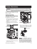
Страница 54: ...d Remove the body s front panel and turn the control panel as shown in section Dismanteling the external panels to page 60 Take off the lid of the sealed chamber Unscrew the connector A to the gas pip...

Страница 55: ...ng will appear on the LCD display Figure 16 5 To set the type of gas enter programming by pressing the reset button 6 in Figure 16 4 for 15 seconds until parameter P01 appears on the LCD display the f...

Страница 56: ...heconfirmation that it was stored occurs automatically after 5 seconds with OK appearing on the LCD display Figure 16 11 Gas setting second step Press the reset button 6 Figure 16 4 to access the vali...

Страница 57: ...rom the boiler Figure 16 14 7 Calibrate the gas valve according to the instructions provided in the section Operations and gas setting on page 56 Reposition the controls panel and remount the front pa...

Страница 58: ...tsoever for cleaning maintenance opening or dismantling of boiler panels 17 2 Dismanteling the external panels Front Panel Loosen the three screws A Fig 17 1 Lift and remove the panel Side Panels Loos...

Страница 59: ...anger and burner To remove the burner fan group D Fig 17 6 Take off the front and side panels of the case Remove the sealed chamber lid Disconnect the connectors of the ignition electrodes E and detec...

Страница 60: ...istle paintbrush To reach the burner do the operations described in the section 17 6 of this manual checked periodically at least once a year During the check the intake and exhaust screens should be...

Страница 61: ...Figure 17 8 A D E 17 16 Setting the boiler chimney sweep function With the boiler set in chimney sweep mode it is possible to exclude some boiler automatic functions making check and control operatio...

Страница 62: ...g the valid parameter P09 for the Chimney cleaning mode setting the following will appear on the LCD display the sequence P09 alternates with 00 Figure 17 12 Turn the hot water temperature adjustment...

Страница 63: ...hown in Figure 17 16 Figure 17 16 MIN MAX 8 The LCD display signals the variation with the symbols shown in the following figure turning on alternately Example heating thermal power at maximum Figure...

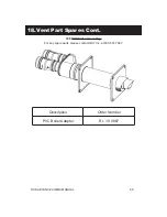
Страница 64: ...RIVA ADVANCE COMBI MANUAL 64 18 Vent Part Spares Cont 18 2 Coaxial venting Description Order Number Coaxial flue kit 10999 0387 0 For any spare parts please contact QHT Inc at 800 501 7697...

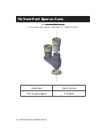
Страница 65: ...RIVA ADVANCE COMBI MANUAL 65 18 Vent Part Spares Cont 18 4 Separate PVC venting For any spare parts please contact QHT Inc at 800 501 7697 Description Order Number PVC Boiler Adapter PTA5808...

Страница 66: ...66 RIVA ADVANCE COMBI MANUAL 18 Vent Part Spares Cont 18 5 PVC Sidewall venting For any spare parts please contact QHT Inc at 800 501 7697 Description Order Number PVC Boiler Adapter RI 10 0887...

Страница 67: ...RIVA ADVANCE COMBI MANUAL 67 18 Vent Part Spares Cont Description Order Number PVC Boiler Adapter RI 10 0885 18 6 PVC Roof venting For any spare parts please contact QHT Inc at 800 501 7697...

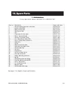
Страница 68: ...6 11 D h w temperature probe NTC BI1001 117 12 Gas valve BI1253 119 14 Pump BI1262 137 15 Main circuit drain valve BI1011 104 16 Automatic air purger valve BI1212 107 17 Condensate trap BI1442 104 18...

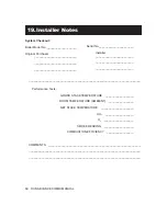
Страница 69: ...______________________________________________________ Performance Tests GROSS STACK TEMPERATURE __________________ ROOM TEMPERATURE AMBIENT ________________ NET STACK TEMPERATURE ____________________...

Страница 70: ...RIVA ADVANCE COMBI MANUAL 70 NOTE...

Страница 71: ...71 RIVA ADVANCE COMBI MANUAL NOTE...

Страница 72: ...1796220630 17962 2063 0 2712 76A4 USA 06 07 2012 N...

Отзывы: