12
CONFIGURATION
CONFIGURATION OPTIONS SCREEN
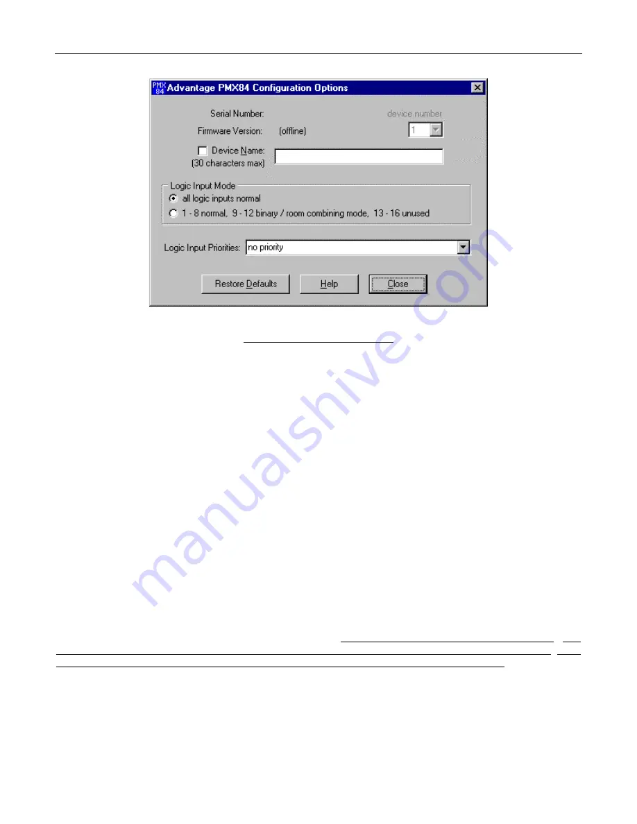
The Configuration Options screen has three sections. The top section displays the Serial Number & Firmware Version for the current
PMX84 (if operating ‘on-line’). The PC Control Software can operate ‘off-line’ (with no product connected) by opening a ‘new’ file for the
desired product. The Serial Number & Firmware Version are not displayed for ‘new’ (off-line) files. Left-clicking Device Number opens a
drop-down menu which allows assignment of an ‘address’ number (1~8). When more than one PMX84 is used in a system, their serial
ports may be connected together (see Computer Control on pg. 14). Under these circumstances, RS-232 commands (from computer or
certain third-party controllers) may be routed to specific PMX84s in the system, using their Device Numbers. Left-clicking Device Name
allows a custom name to be given to the PMX84, by entering up to 30 characters of text. The middle section of the screen selects the
Logic Input Mode. Left-clicking all logic inputs normal allows all Logic Inputs to operate independently, except for priority as described
below. Left-clicking 1-8 normal, 9-12 binary/room combining mode, 13-16 unused instead reconfigures Logic Inputs 9~12 for ‘room
combining’ applications, utilizing one Logic Input (switch) for each room partition. This supports up to four rooms, with sixteen possible
combinations of ‘open’ or ‘closed’ partitions. Under these circumstances, button definitions are created which perform the appropriate
Matrix Switch (input/output) assignments when specific room partitions are moved (switches ‘opened’). In the binary/room combining
mode, Logic Inputs 1~8 operate normally, however, Logic Inputs 13~16 are unused (disabled). The bottom section of the screen selects
the desired grouping of Logic Input Priorities. Left-clicking the adjacent arrow button opens a drop-down menu of seven different priority
schemes for the Logic Inputs. Logic Input Priority allows the PMX84 to establish a priority scheme suitable to a particular application. The
Logic Inputs may be assigned in single or multiple groups, with each group having 4 or 8 priority levels. Within each group, the lower
numbered Logic Input has highest priority. Logic Inputs are affected by priority only within these groups. (Example: ‘Four Groups of Four
Priority’ would work well when four levels of paging priority are required in four independent paging zones. Where Logic Inputs 1, 5, 9, &
13 represent the highest ‘emergency’ priority level, Logic Inputs 2, 6, 10, & 14 represent the second ‘all-call’ priority level, Logic Inputs 3, 7,
11, & 15 represent the third ‘local page’ priority level, and Logic Inputs 4, 8, 12, & 16 represent the lowest ‘message repeater’ priority level.
Also, button definitions may be created which automatically select ‘background music’ when no zone paging is present. Left-clicking
Restore Defaults allows all Configuration Options to be restored to their factory default settings. Left-clicking Help provides additional
instruction. Left-clicking Close will return you to the Mix screen. NOTE: Factory default settings are shown on the screen above.
Files
are available for downloading during Configuration, which are designed for specific applications (see Applications on pgs. 16~21). These
files represent typical uses of Logic Input Priority & Logic Input Mode, for paging routing & room combining applications.


