


H-916 SB2 Indoor Cycle
5
ASSEMBLY GUIDE
1. ASSEMBLY INSTRUCTIONS
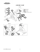
(Figure 1).The assistance of a second person is
recommended when assembling this unit. Take the
unit out of its box and verify the parts are undamaged
and quantities are correct.
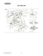
1.
(A) Main body; (B) Handlebar; (C) Handlebar stem;
(H) Saddle post; (G) Horizontal saddle tube; (F)
Saddle; (I) Rear stabilizer bar with adjustable feet; (J)
Front stabilizer bar with wheels; (L) Left pedal; (R)
Right pedal; (M) Monitor casing and components; (10)
Slot head bolt M 10; (9) Flat washer M 10; (8) Cap nut
M 10; Double ended spanner wrench.
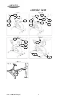
2.
Figure 2. Position the rear stand of main body (A)
on the rear stabilizer bar (I). Insert the bolts (10), fit the
flat washers (9) and cap nuts (8) and then tighten
securely.
3.
Figure 2. Position the front stabilizer bar with
wheels (J), paying attention to the red dots and with
the wheels facing forwards. Insert the bolts (10), fit the
flat washers (9) and cap nuts (8) and tighten securely.
2. FIT THE PEDALS
The assembly instructions for the pedals must be
followed exactly, fitting these incorrectly could
damage the screw thread on either the pedal or
the crank.
Right and left refer to the position that the user adopts
when sitting on the saddle to do the exercises.
Figure 3. The right pedal, marked with the letter (R),
screws onto the right crank, also marked with an (R),
in a clockwise direction. Tighten securely.
Figure 3. The left pedal, marked with the letter (L),
screws onto the left crank, also marked with an (L), in
an counterclockwise direction. Tighten securely.
3. ATTACH THE SADDLE
Figure 4. Fit the saddle bracket (F), onto the horizontal
saddle tube (G). Fit the saddle into position and
tighten the nuts onto the bracket securely. Next insert
the horizontal saddle tube (G) through the hole on the
saddle post (H).
Figure 5. Position it correctly and tighten the knob (S).
Insert the saddle post (H) into the boss on the main
body (A), position it comfortable for doing exercise and
tighten the saddle post by using the adjustment knob
(T) turning it clockwise.
ADJUST THE SADDLE HEIGHT
Figure 4. Loosen the saddle post adjustment knob (T)
slightly by turning it counterclockwise, move the
saddle to a position comfortable for doing exercise
and then tighten the adjustment knob (T) securely by
turning it clockwise.
HORIZONTAL ADJUSTMENT OF THE SADDLE
Figure 5. Loosen the knob (S) slightly by turning it
counterclockwise. Move the saddle to a position
comfortable for doing exercise and then tighten the
knob (S) securely by turning it clockwise.
4. FIT THE HANDLEBAR
Figure 5. Position the handlebar (B) on the handlebar
stem (C). Tighten the knob (V) and then insert the
handlebar stem (C) into the hole on the main body (A).
Position it correctly and then tighten knob (Y) by
turning it clockwise.
ADJUST THE HANDLEBAR HORIZONTALLY
Figure 5. Position the handlebar (B) at a comfortable
distance for doing exercise but without going beyond
the “MAX” marks, now tighten knob (V) securely.
ADJUST THE HANDLEBAR VERTICALLY
Figure 5. Position the handlebar (B) at a comfortable
distance for doing exercise but without going beyond
the “MAX” marks, now tighten knob (Y) securely.
5. ATTACH THE MONITOR
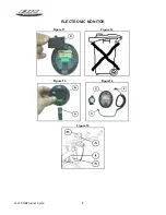
Figure 6. Fit the monitor (m) into the bracket (n). Take
the middle cable and connect terminal (h) to terminal
(k), coming out of the bottom of the main body (A).
Insert the jack on the middle cable into the back of the
monitor (see the following instructions for the monitor).
EXERTION SETTINGS
Figure 7. To provide an even level of exertion during
exercise, this appliance is equipped with a tensioning
control (Z), located on the stem of the main body (A).
This provides various exertion settings when turned.
To increase/decrease pedal resistance turn the
tensioning control (Z) until the exertion level best suits
your exercise requirements.
During exercise the flywheel will get hot due to the
braking effect, so when you have finished exercising it
is advisable to set the tensioning control (Z) to
minimum in order to help stop the brake shoe from
hardening.
Important:
Figure 7. This tensioning control (Z) is equipped with
an emergency braking system which, when applied
with force (as shown by the arrow in Figure 7),
produces a much sharper braking effect.