SW-Stahl und Werkzeugvertriebs GmbH
Tel. +49 (0) 2191 / 46438-0
F
5 6
e s s a r t S r e s u k r e v e L
ax +49 (0) 2191 / 46438-40
e d . l h a t s w s
@
o f n i : l i a
M - E
d i e h c s
m
e R 7 9 8 2 4 - D
Instruction Manual
BGS technic KG
Bandwirkerstr. 3
D-42929 Wermelskirchen
Tel.: 02196 720480
Fax.: 02196 7204820
www.bgstechnic.com
OPERATION
NOTE
: The technique required for removal of the in je ct or will depend on which system is fitted to the
vehicle. Always use an external adaptor first if possible. If by using reasonable force the in je ct or cannot
be removed, use an internal adaptor. Before working on the fuel system, make sure that the fuel system is
NOT pressurised. Refer to the manufacturer's instruction manual on how to de-pressurise the system.
Disconnect the injector wires and connections as per the manufacturer's instructions. Remove any carbon
build up from around the injector. Remove the electrical unit from the injector.
NOTE
: When connecting the ball joint adapter to the outer thread adapter, keep the ball joint adapter in the
correct position. To protect the threads, all fittings must be tightened.
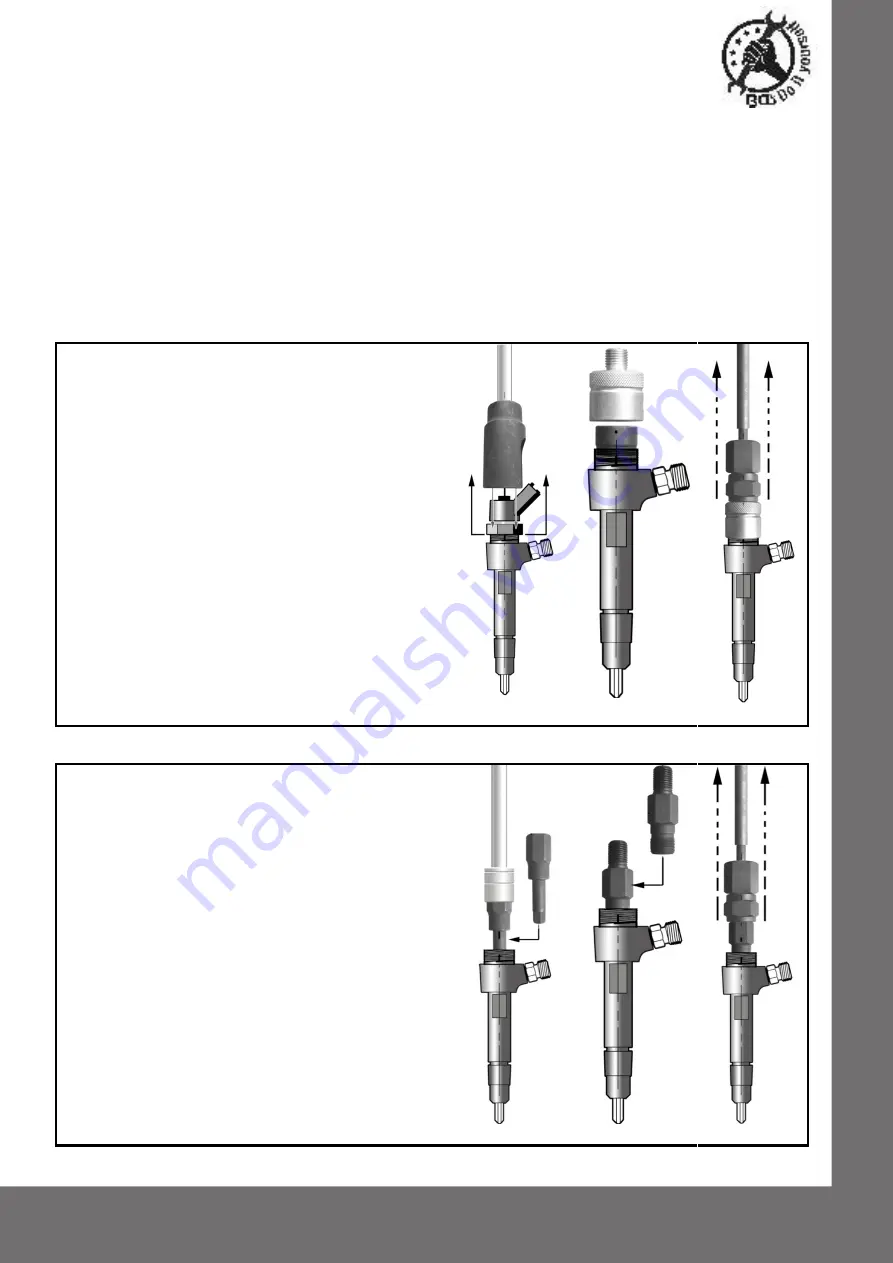
USING OUTER THREAD ADAPTOR
1. Disassemble the electromagnet of the injector with
tool (No.8). (see A).
2. Choose the outer thread adaptor (No.6) and
separate the inner black part from the outer silver
part by removing the screw from the top of the
adaptor.
3. Position the black part inside the top of the injector
(see B) then place the silver part over it, and screw
it down firmly onto the external threads. Install the
screw securely thus locking the adaptor parts
tightly together with the injector thread and wall in
between. This ensures a more secure fastening
and reduces damage to the injector threads.
4. Connect sliding hammer (No.1-2-3), ball joint
adaptor (No.4) and outer thread adaptor (No.6)
(see C).
5. The injector can now be removed with appropriate
slide hammer strokes.
It is recommended to replace the injectors, which are
removed with a slide hammer.
A
B
C
USING INNER THREAD ADAPTOR
1. Disassemble electromagnet of injector with tool
(No.8).
2. Remove pull disc of the injector needle.
3. Insert and turn anti-clockwise the tool (No.7) to
remove the inner sleeve (see D).
4. Screw the appropriate internal adaptor (No.5) into
the threads of the injector and tighten with a
suitable spanner (see E).
5. Connect sliding hammer (No.1-2-3), ball joint
adaptor (No.4) and inner thread adaptor (No.5)
(see F).
6. The injector can now be removed with appropriate
slide hammer strokes.
It is recommended to replace the injectors, which are
removed with a slide hammer.
D
E
F


