background image

english

15

General information

1. The antenna connectors 

���

are provided with a direct voltage of 8.3 V DC. In order to avoid a

short circuit, they should not touch the housing of the rack.  

2. Use high-quality 50 

Ω

coaxial cables. The longer the cable, the higher the attenuation of the RF

signal. For long distances we recommed Aircell 7, Ecoflex 10 or 15 cables to minimise signal loss.

3. To connect remote antennas, use normal 50 

Ω

coaxial cables. The longer the cable, the higher

the RF signal loss. Therefore, the cable length should not exceed 6 m. The larger the diameter of
cable, the lower the signal loss. If you need cables longer than 6 m you should therefore use
cables with a larger diameter to reduce the loss of signal.

4. Connected antennas must operate in the same frequency range of 480 - 800 MHz as the 

antenna splitter.

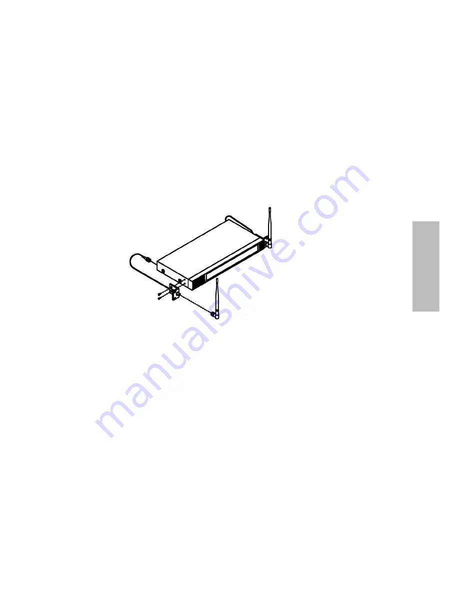
UHF antenna

Front antenna mounting 
bracket (FB 30)

Содержание ZAS 900

Страница 1: ...ZAS 900 UHF Antennensplitter Antenna Splitter Splitter d antenne BEDIENUNGSANLEITUNG OPERATING INSTRUCTIONS NOTICE D UTILISATION...

Страница 2: ......

Страница 3: ...nelemente und Funktionen Seite 6 Installation Seite 7 Allgemeine Hinweise Seite 9 Safety Instructions Page 10 Features Page 12 Supplied accessories Page 12 Controls indicators and functions Page 12 In...

Страница 4: ...and darauf treten oder Kabel geknickt werden k nnen 11 Verwenden Sie nur vom Hersteller mitgeliefertes bzw empfohlenes Zubeh r 12 Nehmen Sie das Ger t bei einem Gewitter oder wenn es l ngere Zeit nich...

Страница 5: ...ten d rfen nur von autorisiertem Fachpersonal durchgef hrt werden Dieses Symbol warnt vor nicht isolierten spannungsf hrenden Teilen die sich im Inneren des Ger ts befinden Beim Ber hren dieser Teile...

Страница 6: ...91 Richtantenne m glich 5 Zus tzlich zu den jeweils vier gesplitteten Antennenausg ngen steht jeweils ein durchge schleifter Anschluss zur Verf gung an den weitere Splitter f r aufw ndigere Installat...

Страница 7: ...en kann Antennensplitterausgang Liefert die Diversity Antennensignale f r bis zu vier Empf nger DC Eingang Zum Anschluss des mitgelieferten 12 V DC Netzteils Installation 2 Anwendungen Erste Anwendung...

Страница 8: ...chkabel mit den Antenneneing ngen der Empf nger verbunden Um den Diversitybetrieb zu gew hrleisten muss jeder Empf nger mit einem A und einem B Antennensignal versorgt werden 4 Verbinden Sie das mitge...

Страница 9: ...nalverluste zu minimieren 3 Zum Anschluss von abgesetzten Antennen verwenden Sie normale 50 Ohm Koaxialkabel Je l nger das Kabel desto gr er ist der HF Signalverlust Die Kabel sollten daher nicht l ng...

Страница 10: ...here they will not be pinched or cut by heavy or sharp objects 11 Only use attachments accessories specified by the manufacturer 12 Disconnect the unit from power during thunderstorms or when not used...

Страница 11: ...ock Leave all service work to authorised expert personnel This symbol indicates that dangerous voltage constituting a risk of electric shock is present within this unit This symbol indicates that ther...

Страница 12: ...nna or AT 91 directional antenna 5 In addition to the four antenna outputs there is a loop through connector to connect further splitters in more extensive installations 6 Both antenna inputs provide...

Страница 13: ...when required Antenna splitter output Supplies the diversity antenna signal for a maximum of four receivers DC input To connect the supplied 12 V DC power adapter Installation 2 applications First app...

Страница 14: ...to the antenna inputs of the receiver by using the supplied TNC cables To ensure the diversity operation each receiver must be supplied with one A and one B antenna signal 4 Connect the supplied powe...

Страница 15: ...lex 10 or 15 cables to minimise signal loss 3 To connect remote antennas use normal 50 coaxial cables The longer the cable the higher the RF signal loss Therefore the cable length should not exceed 6...

Страница 16: ...dier au probl me 10 Posez l ensemble des c bles de sorte ce qu on ne puisse pas marcher dessus ni les craser 11 Utilisez uniquement des accessoires fournis ou recommand s par le fabricant 12 D branche...

Страница 17: ...ent tre uniquement confi es un personnel qualifi agr Ce symbole d avertissement rappelle la pr sence de pi ces sous tension non isol es l int rieur de l appareil Le contact avec ces composants pr sent...

Страница 18: ...es quatre sorties d antenne respectives s par es une sortie boucl e est disposition sur laquelle des s parateurs suppl mentaires peuvent tre raccord s pour des installations plus complexes 6 Les deux...

Страница 19: ...cascade Sortie de s parateur d antenne fournit les signaux d antenne Diversity pour jusqu quatre r cepteurs Entr e DC pour le raccordement de l alimentation 12 V DC fournie Installation 2 application...

Страница 20: ...les patch TNC fournis aux entr es d antenne des r cepteurs Pour assurer le fonctionnement Diversity chaque r cepteur doit tre aliment avec un signal d antenne A et B 4 Branchez l alimentation fournie...

Страница 21: ...es de signal 3 Pour le raccordement d antennes d port es utilisez des c bles coaxiaux 50 ohms normaux Plus le c ble est long plus les pertes de signal HF sont lev es Nous recommandons de ce fait une l...

Страница 22: ...e Illustrations non contractuelles Sous r serve de modifications beyerdynamic GmbH Co KG Theresienstr 8 74072 Heilbronn Germany Tel 49 0 7131 617 0 Fax 49 0 7131 617 204 info beyerdynamic de www beyer...

Отзывы: