background image

IMPORTANT 


Before  you  begin:

  Open,  identify  and  count  all  parts  prior  to  assembly.  Lay  out  parts  on  a  flat  and  non-

abrasive surface. You will need the parts identified on page 4 of this instruction manual. 
 

NOTE:

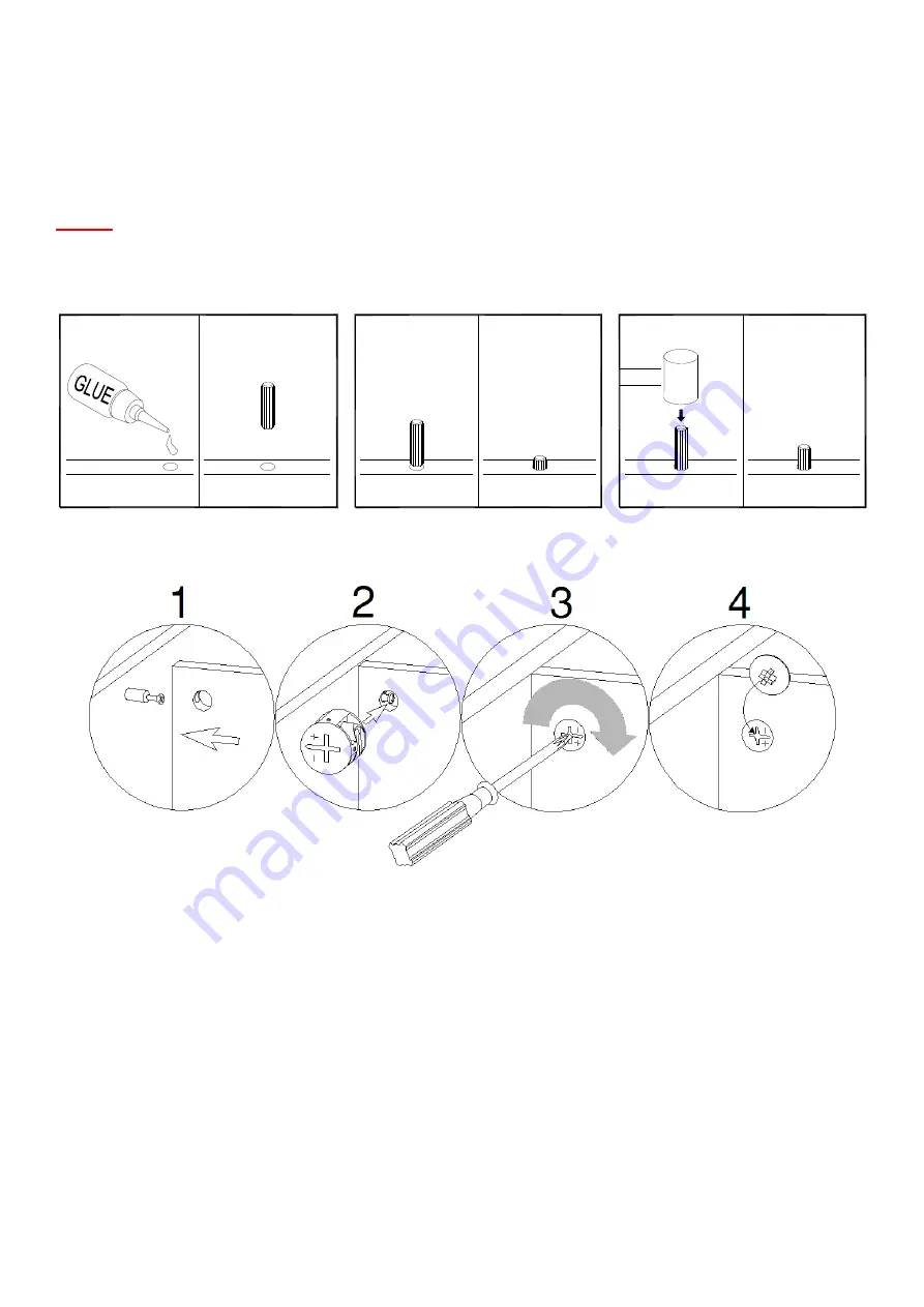
  IT  IS  VERY  IMPORTANT  TO  USE  GLUE  WITH  DOWELS.  EXCESS  GLUE  CAN  BE  WIPED 

OFF WITH DAMP CLOTH. 
 
Insert the Dowel at least half way by tapping lightly with a rubber mallet, IF NECESSARY. 


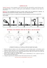
CAM LOCK SYSTEM OPERATION 


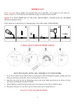
HOW THE KNOCK DOWN (KD) ASSEMBLY SYSTEM WORKS 


1.


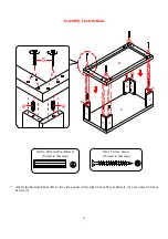
Screw the Cam Bolt into the threaded inserts on the panel. Connect both panels together; making sure Cam 
Bolt goes into the pre-drilled hole on the end of panel for Cam Lock. 

2.


Insert the Cam Lock into the pre-drilled large hole on the panel. Make sure the arrow on the face of Cam 
Lock faces out and points towards Cam Bolt. 

3.


Take a Phillips screwdriver and rotate the Cam Lock clockwise to lock the Cam Bolt in place. 

4.


Plug the Cam Lock Cover into the cross slot of the Cam Lock to conceal the Cam. 


You are now ready to assemble the fireplace. 


X

X

FINAL

1

2

4

3


Содержание BH46-021-399-01

Страница 1: ...f parts are missing DO NOT return this item to the store where it was purchased Please call our customer service number and have your instructions and parts list ready to provide the model name part name or factory number 866 942 5362 Pacific Standard Time 8 30 a m 4 30 p m Monday Friday Or visit our web site 24 hours a day 7 days a week for product assistance at www whalenstyle com Or e mail your...

Страница 2: ...n before discarding Remove all parts from carton and separate into groups as indicated on part list Please ensure all parts are included prior to assembly Use of power tools to complete assembly is not recommended M AXIMUM RECOMMENDED WEIGHT LOADS MAXIMUM LOAD 200 lb 90 7 kg THIS UNIT IS INTENDED ONLY FOR USE WITHIN THE MAXIMUM WEIGHTS INDICATED USE WITH LOADS HEAVIER THAN THE MAXIMUM WEIGHTS INDI...

Страница 3: ...TION HOW THE KNOCK DOWN KD ASSEMBLY SYSTEM WORKS 1 Screw the Cam Bolt into the threaded inserts on the panel Connect both panels together making sure Cam Bolt goes into the pre drilled hole on the end of panel for Cam Lock 2 Insert the Cam Lock into the pre drilled large hole on the panel Make sure the arrow on the face of Cam Lock faces out and points towards Cam Bolt 3 Take a Phillips screwdrive...

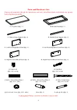
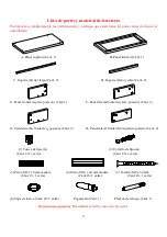
Страница 4: ...t Qty 2 E Left Front Right Back Panel Qty 2 F Left Front Right Back Side Panel Qty 2 G Right Front Left Back Panel Qty 2 H Right Front Left Back Side Panel Qty 2 1 Cam Lock 2 Cam Bolt Qty 24 1 extra Qty 24 1 extra 3 M8 x 30 mm Wood Dowel 4 M10 x 40 mm Wood Dowel 5 M4 x 50 mm Screw Qty 16 1 extra Qty 16 1 extra Qty 26 1 extra 6 Cam Lock Cover Qty 24 1 extra Glue Qty 1 Touch up Pen Qty 1 Tools requi...

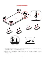
Страница 5: ...l the hardware and required parts Assembly the unit on a carpeted floor or the empty carton to avoid any scratch 2 Securely screw the Cam Bolts 2 into the designated small holes on the Panels A E and G using a Phillips screwdriver 2 A E E G G Cam Bolt 24 used in this step ...

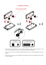
Страница 6: ...n Cam Lock system operation supplement 4 Repeat the previous step to combine the Right Back Side Panel F with the Right Back Panel E together 5 Repeat the same procedure with the Right Front Left Back Side Panels H and Right Front Left Back Panels G together G H 1 x 2 E F 3 1 x 2 3 Cam Lock 8 used in this step M8 x 30 mm Wood Dowel 4 used in this step ...

Страница 7: ...ctions 6 Attach the previous assemblies to the Top Panel A with eight 40 mm Wood Dowels 4 and sixteen Cam Locks 1 as shown Cam Lock 16 used in this step A 4 E F F E G H G H 4 1 M10 x 40 mm Wood Dowel 8 used in this step ...

Страница 8: ...ctions 7 Attach the Bottom Panel B to the side panels with eight 40 mm Wood Dowels 4 and sixteen 50 mm Screws 5 M4 x 50 mm Screw 16 used in this step M10 x 40 mm Wood Dowel 8 used in this step A E F F E G H G H B 4 4 5 ...

Страница 9: ...e Bottom Long Supports C with four 30 mm Wood Dowels 3 9 Fasten the previous assembly to the Bottom Panel B with eight 30 mm Wood Dowels 3 and ten 50 mm Screws 5 B 3 3 3 3 D D C C C C D D 3 5 M8 x 30 mm Wood Dowel 12 used in this step M4 x 50 mm Screw 10 used in this step ...

Страница 10: ...10 Assembly Instructions 10 Stand the assembled unit upright 11 Plug the Cam Lock Covers 6 onto the visible Cams Locks to conceal the cams 6 Cam Lock Cover 24 used in this step ...

Страница 11: ...environment Extreme temperature and humidity changes can cause fading warping shrinking and splitting of wood It is advised to keep furniture away from direct sunlight as sun may damage the finish Proper care and cleaning at home will extend the life of your purchase Following these important and helpful tips will enhance your furniture as it ages A Touch up Pen has been provided to repair any sma...

Страница 12: ......

Страница 13: ...tante no retorne este producto a la tienda en que lo compró Por favor llame a nuestro departamento de ayuda al cliente teniendo su instructivo y lista de partes para proveer el modelo nombre de parte o el número de fábrica 866 942 5362 Hora Estandar del Pacífico 8 30 a m 4 30 p m de Lunes a Viernes O visite nuestra página de Internet 24 horas al dia 7 días a la semana para asistencia www whalensty...

Страница 14: ...r todas las partes del cartón y separar en grupos como es indicado en la lista de partes Por favor de asegurar que todas las partes estan presentes antes del ensamble El uso de herramientas eléctricas para completer el ensamble no es recomendado MÁXIMOS PESOS RECOME NDADOS MÁXIMA CARGA 200 lb 90 7 kg MÁXIMA CARGA 50 lb 22 6 kg ESTA UNIDAD DEBE UTILIZARSE CON LOS PESOS MÁXIMOS INDICADOS SI SE EXCED...

Страница 15: ...N CÓMO FUNCIONA LA INSTALACIÓN DE MONTAJE KD 1 Fijar los tornillos de fijación en los orificios pequeños Conectar ambos paneles cerciorandose que los tornillos de fijación entren bien y que estos queden en los orificios al final del panel con tuercas de fijación 2 Inserte las tuercas de fijación en los orificios grandes del panel Hacer que la flecha en la tuerca este apuntando hacia la entrada del...

Страница 16: ...terior Cant 2 F Panel lateral frontal izq der posterior Cant 2 G Panel derecho frontal izq posterior Cant 2 H Panel lateral frontal der izquierdo posterior Cant 2 1 Tuerca de fijación 2 Tornillo de fijación Cant 24 1 extra Cant 24 1 extra 3 Perno M8 x 30 mm madera 4 Perno M10 x 40 mm madera 5 Tornillo M4 x 50 mm Cant 16 1 extra Cant 16 1 extra Cant 26 1 extra 6 Tapa de tuerca Cant 24 1 extra Pegam...

Страница 17: ...e ferretería y partes requeridas Ensamblar la unidad en un piso alfombrado o en el cartón vacío para evitar rasguños 2 Ajuste los tornillos de fijación 2 en los orificios pequeños designados en los paneles A E y G con un desarmador estrella 2 A E E G G Tornillo de fijación 24 usados en este paso ...

Страница 18: ...ción y su operación 4 Repita el paso anterior para combinar el panel lateral posterior derecho F con el panel posterior derecho E juntamente 5 Repetir el mismo procedimiento con los paneles laterales frontales derechos posterior izquierdos H y los paneles frontales derecho izquierdo posteriores G juntamente G H 1 x 2 E F 3 1 x 2 3 Tuerca de fijación 8 usados en este paso Perno M8 x 30 mm de madera...

Страница 19: ... montajes anteriores al panel superior A con ocho pernos de 40 mm de madera 4 y dieciséis tuercas de fijación 1 como se muestra Tuerca de fijación 16 usados en este paso A 4 E F F E G H G H 4 1 Perno M10 x 40 mm de madera 8 usados en este paso ...

Страница 20: ...que el panel inferior B a los paneles laterales con ocho pernos de 40 mm de madera 4 y dieciséis tornillos de 50 mm 5 Tornillo M4 x 50 mm 16 usados en este paso Perno M10 x 40 mm de madera 8 usados en este paso A E F F E G H G H B 4 4 5 ...

Страница 21: ...feriores largos C con cuatro pernos de 30 mm de madera 3 9 Sujetar el sistema anterior al panel inferior B con ocho pernos de 30 mm de madera 3 y diez tornillos de 50 mm 5 B 3 3 3 3 D D C C C C D D 3 5 Perno M8 x 30 mm de madera 12 usados en este paso Tornillo M4 x 50 mm 10 usados en este paso ...

Страница 22: ...0 Instrucciones de ensamble 10 Poner la unidad en posición vertical 11 Cubrir con las tapas de tuerca de fijación 6 las tuercas que esten visibles para ocultarlas 6 Tapa de tuerca 24 usados en este paso ...

Страница 23: ...que se contraigan o que la madera se parte Es recomendable mantener la unidad lejos del sol directo ya que puede dañar el acabado Los cuidados adecuados y limpieza pueden extender la vida útil de su unidad Siga estás recomendaciones y mantendrá su mueble en buenas condiciones de uso por muchos años Un plumón de retoque es proveído en caso de pequeñas raspaduras o golpes que sucedan durante el ensa...

Страница 24: ......

Отзывы: