


Beton Trowel nv
Nijverheidsstraat 11
1840 Londerzeel/Belgium
Tel: +32 (0)52 315 350 - Tel: +32 (0)52 315 351
Fax: +32 (0)52 303 739
E-mail: [email protected]
BE 0821.249.312
www.betontrowel.com
BNP FORTIS:
ING:
BE81 0015 9813 5624
BE
- GEBABEBB
BBRUBEBB
Pag.
7/39
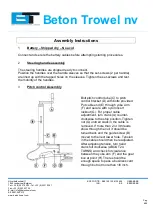
4
Seat Assembly
Remove protective wrapping from seat. The seat is now ready to secure to the frame
using included washers and hex nuts. If the seat adjuster is ordered, the slider bars
must be positioned between the seat and the frame using included screws to secure
the seat to the sliders, and then securing the sliders to the frame as indicated above.
5
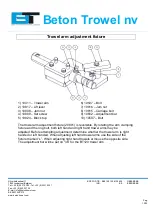
Transporter Assembly
The components of the are detailed in the parts drawing within this manual (pg. 34).
The assembly of the transporter consists of only the wheel and pin, and the main
transporter body. This transporter is shipped with very little assembly required.
CAUTION: The transporter is designed to be used on the job site only.
Do not use the transporter to tow the machine off-site.


