background image

7

USA

CURRENT SPEED FUNCTION

This information is constantly displayed to-
gether with an indication provided by a
graphic bar. The default unit is Mph. To
change the unit, press the button to access
the Setup menu and select km/h. When Mph
is selected, no indication is provided as to
which unit is currently displayed.

1 - TIME FUNCTION (TIME)
T

 3” and Vel=0 activates time setting mode

T<3” or Vel>0 cycles through functions
The time can only be set while the vehicle is stationary.
Press and hold button C or D for more than 3 seconds to enter the time setting mode.
Once the time has been set, press the button for about 3 seconds to go back to the
standard operating mode. The Time parameter is displayed in the 0-12 format if Mph
has been selected, and in the 0-24 format if Km/h has been chosen. When in the setting
menu, if no buttons are pressed for 20 seconds the system will automatically return to the
standard operating mode.
Moving off (Vel > 0) while the setting mode is activated causes the system to automati-
cally return to the standard operating mode.

2 - AUTOMATIC LAP FUNCTION (LAP)
T

 3” resets LAP and TD

T<3” cycles through functions
This information represents the actual riding time associated with the TD parameter. It is
an automatic counter which is activated by the first pulse generated by the speed sensor
and stops 3 seconds after receiving the last pulse from the sensor. The counter for this
parameter can be reset while in LAP mode by pressing the C or D button for about 3
seconds until 00’00” is displayed. The LAP function can be reset while the vehicle is
stationary or in motion and also causes the reset of the TD parameter.

3 - MILEOMETER FUNCTION (TOD)
T

 3” and Vel=0 enables setting of circumference, unit and number of pulses for each wheel turn

T<3” or Vel>0 cycles through functions
The information is displayed together with the TOD caption. Depending on the selected unit, the
informat is displayed in Mph (default) or Km/h and is permanently stored in non-volatile memory.
It is not possible to reset this information during normal operation of the instruments.

Содержание RR4T USA 400

Страница 1: ...RR4T USA RS4T USA 400 450 525 ...

Страница 2: ......

Страница 3: ...ates to the Europe version Label location RR4T USA 2 Label location RS4T USA 3 Controls RR4T USA 4 Controls RS4T USA 5 Digital speedometer RR4T USA RS4T USA 6 Wiring diagram RR4T USA 10 Wiring diagram RS4T USA 12 Fuel cock 14 Choke 15 Adjusting the slow running 15 Canister filter 16 ...

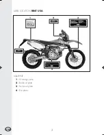
Страница 4: ...2 USA LABEL LOCATION RR4T USA Label RR4T 1 Warnings plate 2 Brake oil plate 3 Technical plate 4 Eco plate 4 1 2 2 3 ...

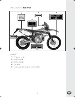
Страница 5: ...3 USA label RS4T 1 Warnings plate 2 Brake oil plate 3 Technical plate 4 Eco plate 5 Vapour recovery diagram under saddle 1 4 3 5 2 LABEL LOCATION RS4T USA 2 ...

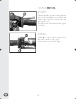
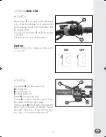
Страница 6: ...ide of the handlebars and operate the electri engine starter Push the button until the engine sterts Do not press the button 1 while the engine is running LH SWITCH Switch 2 is used to stop the engine Press the button until the engine stops While button 3 turns on the lights 1 3 2 ...

Страница 7: ... turns off the engine Caution Before turning it on make sure the switch 2 is on ON LH SWITCH Dip switch 3 has three positions A lights off B low beam on C high beam on Button 4 operates the horn Switch 5 is used to stop the engine Press the button until the engine stops Shifting lever 6 left or right activates the left or right indicators if istalled When released the returns to the central posi t...

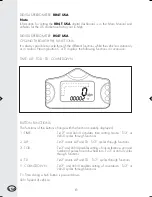
Страница 8: ...TIME LAP TOD TD COUNTDOWN BUTTON FUNCTIONS The functions of the buttons change with the function currently displayed 1 TIME T 3 and Vel 0 activates time setting mode T 3 or Vel 0 cycles through functions 2 LAP T 3 resets LAP and TD T 3 cycles through functions 3 TOD T 3 and Vel 0 enables setting of circumference unit and number of pulses for each wheel turn T 3 or Vel 0 cycles through functions 4 ...

Страница 9: ...el 0 while the setting mode is activated causes the system to automati cally return to the standard operating mode 2 AUTOMATIC LAP FUNCTION LAP T 3 resets LAP and TD T 3 cycles through functions This information represents the actual riding time associated with the TD parameter It is an automatic counter which is activated by the first pulse generated by the speed sensor and stops 3 seconds after ...

Страница 10: ...lways active and is automatically decreased by 0 1 kilometres or miles according to the selected unit The value for this parameter can be changed in TD decrease mode by pressing the button for about 3 seconds while the vehicle is stationary The different figures that make up the counter can be altered starting from the most significant figure and shifting in successive steps to the least significa...

Страница 11: ...nal from the speed sensor The button is depressed As soon as the microcontroller wakes up the following happens The display and the warning lights are checked all the warning lights come up provid ing that power is supplied by the vehicle for about 2 seconds The selected wheel circumference and number of wheel pulses are displayed for about 2 seconds The last function in use when the system went i...

Страница 12: ...10 USA WIRING DIAGRAM RR4T USA ...

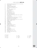
Страница 13: ...REGULATOR 12 ELECTROVALVE KIT OPTIONAL 13 TAIL LAMP LED 14 FUSE 10 A 15 EARTH BRAID 16 POSITIVE BATTERY 17 STARTER RELAY 18 STARTER MOTOR 19 NEGATIVE BATTERY 20 BATTERY 12V 4AH 21 PICK UP 22 ELECTRONIC CONTROL UNIT 23 AT COIL 24 SPARK PLUG 25 EARTH CONNECTION FRAME 26 POSITION LAMP 12V 5W 27 HEADLAMP 12V 35 35W Key to colours Bi White Ve Green Ma Brown Vi Purple Bl Blue Ne Black Gi Yellow Rs Red A...

Страница 14: ...12 USA WIRING DIAGRAM RS4T USA ...

Страница 15: ...8 12V REGULATOR 19 LEFT HAND REAR TURN INDICATOR 12V 10W BULB 20 NUMBER PLATE LIGHT 12V 5W BULB 21 REAR LIGHT 12V 5 21W BULB 22 RIGHT HAND REAR TURN INDICATOR 12V 10W BULB 23 BATTERY POSITIVE TERMINAL 24 BATTERY 12V 4Ah 25 GENERATOR 26 10A FUSE 27 EARTH BRAID 28 STARTER RELAY 29 STARTER MOTOR 30 BATTERY NEGATIVE TERMINAL 31 REAR STOP LAMP RELAY 32 ELECTRONIC CONTROL UNIT 33 HV COIL 34 SPARK PLUG 3...

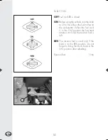
Страница 16: ...ws the fuel to flow to the carburettor When the fuel cock is in the ON position the fuel tank empties until only the reserve fuel is left RES The reserve fuel is used only if the knob is in the RES position Do not forget to bring the knob back to the ON position after refuelling Reserve fuel 1 litre 1 ...

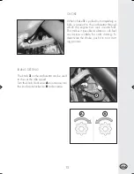
Страница 17: ...ase turn the knob anticlockwise B to decrease CHOKE When choke 1 is pulled out completely a hole is opened in the carburettor through which the engine can suck in extra fuel This makes it possible to obtain a rich fuel air mixture suitable for cold starting To deactivate the choke push it in to its start ing position 1 2 A B ...

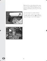
Страница 18: ...rotection and all vehicles comply with the applicable regu lations on harmful gas emissions and sound pollution CANISTER RS4T USA FILTER SYSTEM The extra system with a Canister 1 emis sion filter and vacuum valve 2 prevent the release of vapours into the atmosphere 2 1 ...

Страница 19: ......

Страница 20: ...Cod 21 73289 000 ...

Отзывы: