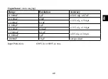
background image

EN

Peak Hold button

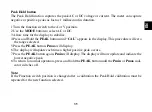
The.Peak.Hold.function.captures.the.peak.AC.or.DC.voltage.or.current..The.meter.can.capture.

negative.or.positive.peaks.as.fast.as.1.millisecond.in.duration...

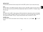
Turn.the.function.switch.to.the.A.or.V.position.

Use.the.

MODE

.button.to.select.AC.or.DC.

Allow.time.for.the.display.to.stabilize.

Press.and.Hold.the.

PEAK

.button.until.“

CAL

”.appears.in.the.display..This.procedure.will.zero.

the.range.selected.

Press.the.

PEAK

.button,.

Pmax

.will.display.

The.display.will.update.each.time.a.higher.positive.peak.occurs.

Press.the.

PEAK

.button.again,.

Pmin

.will.display..The.display.will.now.update.and.indicate.the.

lowest.negative.peak.

To.return.to.normal.operation,.press.and.hold.the.

PEAK

.button.until.the.

Pmin

.or.

Pmax

.indi-

cator.switches.off.

Note: 

If.the.Function.switch.position.is.changed.after.a.calibration.the.Peak.Hold.calibration.must.be.

repeated.for.the.new.function.selected.

1

2

3

4

5

6

7

8

Содержание 017600020

Страница 1: ...TÍMETRO DE CALIBRACIÓN AUTOMÁTICA TURE RMS MOD 1760 RMS MULTIMETRE RMS VRAI A SELECTION DE PLAGE AUTOMATIQUE MOD 1760 RMS FRA ES AUTO JALON TURE RMS MULTIMETER MOD 1760 RMS TURE RMS MULTIMETER MIT AUTOMATISCHER BEREICHSAUSWAHL MOD 1760 RMS DE NL PL MULTIMETR Z TRUE RMS I FUNKCJĄ AUTORANGING MOD 1760 RMS ...

Страница 2: ...9 Misurazioni di resitenza 12 Controllo continuità 12 Test di diodi 13 Misurazioni della capacitanza 14 Misurazione di frequenza 15 Misurazione di temperatura 15 Caratteristiche tecniche 16 Installazione della batteria 26 Sostituzione dei fusibili 27 MULTIMETRO AUTORANGING A VALORE RMS MOD 1760 RMS ...

Страница 3: ...puntali prima di riposizionare il selettore delle funzioni Tutte le tensioni esterne devono essere scollegate dall apparecchio prima di togliere la batteria I cavi e i puntali devono essere tenuti in buono stato puliti e con l isolamento intatto La UK Safety Authorities l Autorità per la Sicurezza del Regno Unito raccomanda che i cavi del multimetro siano muniti di fusibili durante la misurazione ...

Страница 4: ...e pericolosa la quale se non evitata potrebbe causare morte o lesioni gravi Questo simbolo diAVVISO indica una situazione potenzialmente pericolosa la quale se non evitata potrebbe danneggiare il prodotto Questo simbolo avverte l utente che i terminali così contrassegnati non devono essere collegati a un punto del circuito nel quale la differenza di potenziale verso terra ecceda in questo caso i 6...

Страница 5: ...st dei diodi HOLD Ritenuta dati AUTO Range automatico AC Corrente alternata DC Corrente continua MAX MIN Memorizza il valore più alto o il più basso PEAK Trova i falsi segnali e i transienti brevi Retroilluminazione V Volts A mA µA Intervalli di corrente ...

Страница 6: ... di spegnimento automatico se non viene utilizzato per 15 minuti Nota Nelle modalità di misura più sensibili se i cavi non sono collegati a un dispositivo il display po trebbe indicare una lettura aleatoria Tutto ciò è normale e dovuto alla alta sensibilità di ingresso La lettura si stabilizzerà e darà una misura appropriata quando collegata a un circuito Pulsante MODE Per selezionare misurazioni ...

Страница 7: ...remere nuovamente il pulsante BACKLIGHT per spegnere l illuminazione Pulsante MAX MIN La funzione MAX MIN permette al multimetro di acquisire il valore massimo e minimo per una consultazione successiva Premere il pulsante MAX MIN per avviare la misurazione L indicazione MAX o MIN apparirà sul display Se l indicazione MAX MIN lampeggia l apparecchio si trova in modalità MAX MIN ma non sta registran...

Страница 8: ...are il messaggio CAL sul display Tale procedura azzererà la modalità selezionata Premere il pulsante PEAK sul display apparirà Pmax Il display si aggiornerà ogni qualvolta si presenterà un picco positivo superiore Premere nuovamente il pulsante PEAK sul display apparirà Pmin A questo punto il display si aggiornerà e indicherà il picco negativo più basso Per tornare a operazioni normali tenere prem...

Страница 9: ...per muoversi da un opzione all altra fino a trovare quella desi derata Tenere premuto il pulsante RANGE per 2 secondi per abbandonare la modalità manuale ManualRanging e tornare a quella automatica AutoRanging MISURAZIONE TENSIONE CONTINUA E ALTERNATA Inserire il cavo nero nel terminale negativo COM e il cavo rosso nel terminale positivo V Posizionare il selettore sulla posizione VAC corrente alte...

Страница 10: ...A Per misurazioni fino a 10A in corrente continua posizionare il selettore nella posizione A e inserire il cavo rosso nel jack 10A Tenere premuto il pulsante MODE finché appare DC sul display Togliere la corrente dal circuito da testare Aprire il circuito nel punto in cui si desidera misurare la corrente Toccare con il puntale nero la parte negativa del circuito Toccare con il puntale rosso la par...

Страница 11: ...corrente alternata posizionare il selettore nella posizione A e inserire il cavo rosso a spina unipolare nel jack 10A Premere il pulsante MODE La modalità di misurazione cambierà da tra AC o DC come desi derato Togliere la corrente dal circuito da testare Aprire il circuito nel punto in cui si desidera misurare la corrente Toccare con il puntale nero la parte negativa del circuito Toccare con il p...

Страница 12: ...n lato della parte da testare cosicché il resto del circuito non interferisca con la lettura della resistenza Leggere il valore della resistenza sul display Il display indicherà i decimali i valori e i simboli esatti CONTROLLO DI CONTINUITÀ ATTENZIONE Al fine di evitare folgorazioni non misurare mai la continuità in circuiti o cavi sotto tensione Posizionare il selettore sulla posizione Inserire i...

Страница 13: ... si desidera testare Leggere la misura zione Invertire la polarità cambiando la posizione dei puntali Leggere questa misurazione Il diodo o la giunzione possono essere valutati come segue Se una misurazione visualizza un valore e l altra visualizza OL il diodo funziona Se entrambe le letture visualizzano OL il dispositivo è aperto Se entrambe le letture visualizzano un valore molto piccolo o zero ...

Страница 14: ...ivo CAP Toccare con i puntali la parte da testare Leggere il valore della capacità sul dispaly Il display indicherà i decimali i valori e i simboli esatti Nota Per valori di capacità molto elevati il tempo di misurazione potrà impiegare diversi minuti prima di stabilizzarsi Il display indica DSC quando sta scaricando La scarica attraverso il microcir cuito è alquanto lenta Consigliamo all utente d...

Страница 15: ... ºC o F Inserire la sonda temperatura assicurandosi di mantenere la corretta polarità Tenere premuto il pulsante MODE finché appare ºF o ºC sul display Toccare con il puntale la parte della quale si desidera misurare la temperatura Toccare con i puntali la parte testata finché la lettura si stabilizza circa 30 secondi Leggere la misurazione nel display Nota Il puntale per la misurazione della temp...

Страница 16: ...ti dalla rete di distribuzione elettrica principale aerea o sotterranea Voltaggio massimo tra un qualsiasi terminale e la terra 600Vcc Vca rms Display LCD 11000 Polarità Automatica con indicazione di polarità negativa Controllo over range Indicazione OL Indicazione di batteria Viene visualizzato il simbolo di una batteria quando il livello della scarica batteria scende al di sotto della condizione...

Страница 17: ...ni Operativo 3000m Stoccaggio 10 000m Grado di inquinamento 2 Sicurezza L apparecchio rispetta gli standard IEC EN 61010 1 2001 02 e IEC EN 61010 031 2002 Alimentazione Una batteria da 9V NEDA 1604 IEC 6F22 Dimensioni 182 altezza x 82 larghezza x 55 profondità mm Peso Circa 375g ...

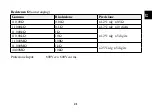
Страница 18: ...cisione 110 00mV 0 01mV 0 8 rdg 10 digits 1 1000V 0 1mV 0 8 rdg 6 digits 11 000V 1mV 110 00V 10mV 600 0V 100mV 1 2 rdg 5 digits Impedenza di entrata 8 98MΩ Input massimo 600Vcc o 600Vca Tensione CA auto ranging Gamma Risoluzione Precisione 110 00mV 0 01mV 1 8 rdg 10 digits 1 1000V 0 1mV 1 5 rdg 10 digits 11 000V 1mV 110 00V 10mV 600 0V 100mV 2 rdg 10 digits ...

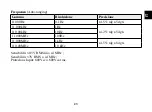
Страница 19: ...ut massimo 600Vcc o 600Vca rms Corrente CC auto ranging Gamma Risoluzione Precisione 110 00µA 0 01µA 1 5 rdg 5 digits 1100 0µA 0 1µA 11 000mA 1µA 1 5 rdg 10 digits 110 00mA 10µA 10 000A 1mA 2 5 rdg 10 digits Protezione da sovraccarico Fusibile 0 2A 600V e 10A 1000V Input massimo 110µA cc su gamma µA 110mA cc su gamma mA 10A cc su gamma 10A ...

Страница 20: ...A 0 01µA 1 8 rdg 8 digits 1100 0µA 0 01µA 11 000mA 1µA 2 0 rdg 10 digits 110 00mA 10µA 10 000A 1mA 3 0 rdg 8 digits Protezione da sovraccarico Fusibile 0 2A 600V e 10A 1000V Frequenza 50Hz 60Hz Input massimo 110µA ca rms su µA 110mA ca rms su mA 10Aca RMS su gamma 10A ...

Страница 21: ...ging Gamma Risoluzione Precisione 110 00Ω 0 01Ω 1 2 rdg 0 5Ω 1 1000kΩ 0 1Ω 1 2 rdg 10 digits 11 000kΩ 1Ω 1 2 rdg 5 digits 110 00kΩ 10Ω 1 1000MΩ 100Ω 11 000MΩ 1kΩ 2 5 rdg 5 digits 40 00MΩ 10kΩ Protezione Input 600Vcc o 600Vca rms ...

Страница 22: ...zione Precisione 11 000nF 1pF 5 0 rdg 0 7nF 110 00nF 10pF 5 0 rdg 20 dgts 1 1000µF 0 1nF 11 000µF 1nF 3 0 rdg 10 dgts 110 00µF 0 01µF 1 1000mF 0 1µF 10 rdg 10 dgts 11 000mF 1µF 40 00mF 10µF non specificato Protezione Input 600Vcc o 600Vca rms ...

Страница 23: ...one Precisione 1100 0Hz 0 1Hz 1 5 rdg 5 dgts 11 000kHz 1Hz 1 2 rdg 5 dgts 110 00kHz 10Hz 1 1000MHz 100Hz 11 000MHz 1kHz 1 5 rdg 8 dgts 110 00MHz 10 kHz Sensibilità 0 5V RMS fino 1MHz Sensibilità 3V RMS a 1MHz Protezione Input 600Vcc o 600Vca rms ...

Страница 24: ... sovraccarico 600V cc o 600Vca rms Test dei diodi Corrente di prova Risoluzione Precisione Normale 1mA Aperto max 3V 1 mV 10 rdg 5 digits Voltaggio a circuito aperto MAX 3V cc Protezione da sovraccarico 600V cc o 600Vca rms Continuità sonora Soglia sonora sotto i 30Ω corrente massima di test 1 5mA Protezione da sovraccarico 600V cc o 600Vca rms ...

Страница 25: ...T Accessori Accessori inclusi Cavi standard Rosso Nero con puntali sonda temperatura di tipo K ATTENZIONE Al fine di evitare folgorazioni non utilizzare il multimetro con lo sportello della batteria aperto ...

Страница 26: ...gare i cavi dal multimetro Aprire lo sportello dell alloggiamento della batteria allentando la vite utilizzate un cacciavite Phillips Inserire la batteria nell alloggiamento mantenendo la corretta polarità Rimettere lo sportello della batteria Bloccarlo con le due viti Nota Se il multimetro non funziona correttamente controllare i fusibili e la batteria per assicurarsi che siano ancora funzionanti...

Страница 27: ...etro utilizzando un cac ciavite Phillips Rimuovere il vecchio fusibile dal suo alloggiamento tirandolo delicatamente Installare il nuovo fusibile nell alloggiamento Utilizzare sempre un fusibile delle giuste dimensioni e voltaggio 0 2 600V rapido per la mo dalità 110mA 10A 1000V rapido per la modalità 10A Rimettere lo sportello del fusibile al suo posto Inserire la vite e stringere ATTENZIONE Al f...

Страница 28: ...rpo esterno dello strumento con uno straccio asciutto Non usare mai sostanze abrasive né solventi In caso di manutenzione utilizzare solo pezzi di ricambio consigliati dal produttore Dichiarazione di Conformità CE Il prodotto 1760 RMS risponde alla direttiva di compatibilità elettromagnetica 2004 108 EC emanata dalla Commissione della Comunità Europea ...

Страница 29: ...rnings 30 Symbols and annunciators 32 Operations 33 DC AC voltage measurement 36 Resistance measurement 38 Continuity check 39 Diode Test 40 Capacitance measurement 41 Frequency measurement 42 Temperature measurement 42 Technical specifications 43 Battery and fuse replacement 52 ...

Страница 30: ...before carrying out resistance tests The rotary selector switch must only be turned after removing test connections All external voltages must be disconnected from the instrument before removing the battery Test leads and prods must be in good order clean and with no broken or cracked insulation UK Safety Authorities recommend the use of fused test leads when measuring voltage on high energy syste...

Страница 31: ...ally hazardous situation which if not avoided could result in death or serious injury This CAUTION symbol indicates a potentially hazardous situation which if not avoided may result damage to the product This symbol advises the user that the terminal s so marked must not be connected to a circuit point at which the voltage with respect to earth ground exceeds in this case 600 VAC or VDC Equipment ...

Страница 32: ...Battery Diode test HOLD Data Hold AUTO AutoRanging AC Alternating Current or Voltage DC Direct Current or Voltage MAX MIN Stores the highest or lowest measurement PEAK Find glitches and transients without a scope Backlight V Volts A mA µA Current range ...

Страница 33: ... OFF that automatically shuts the meter OFF if 15 minutes elapse between uses Note On some lowAC and DC voltage ranges with the test leads not connected to a device the display may show a random changing reading This is normal and is caused by the high input sensitivity The reading will stabilize and give a proper measurement when connected to a circuit MODE button To select AC or DC measurement w...

Страница 34: ...on the display light Press BACKLIGHT button again to exit the light mode MAX MIN button The MAX MIN function allows the meter to capture the highest or lowest measurement for later reference Press the MAX MIN button to begin measurement The indicator MAX or MIN will appear in the display If the MAX MIN messages are flashing the instrument is in MAX MIN mode but not recor ding press the MAX MIN but...

Страница 35: ...appears in the display This procedure will zero the range selected Press the PEAK button Pmax will display The display will update each time a higher positive peak occurs Press the PEAK button again Pmin will display The display will now update and indicate the lowest negative peak To return to normal operation press and hold the PEAK button until the Pmin or Pmax indi cator switches off Note If t...

Страница 36: ... display indicator will turn on Press the RANGE button to step through the available ranges until you select the range you want Press and hold the RANGE button for 2 seconds to exit the ManualRanging mode and return to AutoRanging DC AC VOLTAGE MEASUREMENT Sert the black test lead into the negative COM terminal and the red test lead into the positive V terminal Set the function switch to the VAC o...

Страница 37: ...urrent measurements up to 10A DC set the function switch to the A position and insert the red test lead banana plug into the 10A jack Press the AC DC button until DC appears in the display Remove power from the circuit under test then open up the circuit at the point where you wish to measure current Touch the black test probe tip to the negative side of the circuit Touch the red test probe tip to...

Страница 38: ...ck Press the MODE button The measurement mode will change between AC or DC as required Remove power from the circuit under test then open up the circuit at the point where you wish to measure current Touch the black test probe tip to the negative side of the circuit And touch the red test probe tip to the positive side of the circuit Apply power to the circuit Read the current in the display The d...

Страница 39: ... the resistance in the display The display will indicate the proper decimal point value and symbol CONTINUITY CHECK WARNING To avoid electric shock never measure continuity on circuits or wires that have voltage on them Set the range switch to the position Insert the black lead plug into the COM socket and the red test lead plug into the positive socket Press the MODE button until appears in the d...

Страница 40: ... probe tips to the diode or semiconductor junction you wish to test Note the meter reading Reverse the probe polarity by switching probe position Note this reading The diode or junction can be evaluated as follows If one reading shows a value and the other reading shows OL the diode is good If both readings show OL the device is open If both readings are very small or zero the device is shorted No...

Страница 41: ...ug into the CAP positive jack Touch the test probe tips across the part under test Read the capacitance value in the display The display will indicate the proper decimal point and value Note For very large values of capacitance measurement time can be several minutes before the final reading stabilizes The LCD displays DSC when discharging Discharging through the chip is quite slow We recommend th...

Страница 42: ...ENT Set the function switch to the ºC position Insert the Temperature Probe into the input jacks making sure to observe the correct polarity Press the MODE button until ºF or ºC appears in the display Touch the Temperature Probe head to the part whose temperature you wish to measure Keep the probe touching the part under test until the reading stabilizes about 30 seconds Read the temperature in th...

Страница 43: ...ary supply level overhead or underground utility service Maximun voltage between any terminal and earth ground 600V DC AC RMS Display 11000 counts LCD display Polarity Automatic negative polarity indication Over range OL mark indication Low battery A battery symbol is displayed when the battery voltage drops indication below the operating level Measurement rate 4 times per second nominal Auto powe...

Страница 44: ...ollution degree 2 Safety The instrument complies with IEC EN 61010 1 2001 02 and IEC EN 61010 031 2002 Power One 9V battery NEDA 1604 IEC 6F22 Dimensions 182 H x 82 W x55 D mm Weight Approx 375g Accuracy Accuracy is given at 18 C to 28 C 65 F to 83 F less than 70 RH ...

Страница 45: ... 8 of rdg 6 digits 11 000V 1mV 110 00V 10mV 600 0V 100mV 1 2 of rdg 5 digits Input Impedance 8 98MΩ Maximum Input 600Vdc or 600Vac AC Voltage auto ranging Range Resolution Accuracy 110 00mV 0 01mV 1 8 of rdg 10 digits 1 1000V 0 1mV 1 5 of rdg 10 digits 11 000V 1mV 110 00V 10mV 600 0V 100mV 2 of rdg 10 digits ...

Страница 46: ...ut 600V dc or 600V ac rms DC Current auto ranging Range Resolution Accuracy 110 00µA 0 01µA 1 5 of rdg 5 digits 1100 0µA 0 1µA 11 000mA 1µA 1 5 of rdg 10 digits 110 00mA 10µA 10 000A 1mA 2 5 of rdg 10 digits Overload Protection 0 2A 600V and 10A 1000V Fuse Maximum Input 110µA dc on µA range 110mA dc on mA range 10A dc on 10A range ...

Страница 47: ...1µA 1 8 of rdg 8 digits 1100 0µA 0 1µA 11 000mA 1µA 2 0 of rdg 10 digits 110 00mA 10µA 10 000A 1mA 3 0 of rdg 8 digits Overload Protection 0 2A 600V and 10A 1000V Fuse AC Response 50 Hz to 60 Hz Maximum Input 110µA ac rms on µA 110mA ac rms on mA 10A ac rms on 10A range ...

Страница 48: ...ange Resolution Accuracy 110 00Ω 0 01Ω 1 2 of rdg 0 5Ω 1 1000kΩ 0 1Ω 1 2 of rdg 10 digits 11 000kΩ 1Ω 1 2 of rdg 5 digits 110 00kΩ 10Ω 1 1000MΩ 100Ω 11 000MΩ 1kΩ 2 5 of rdg 5 digits 40 00MΩ 10kΩ Input Protection 600V dc or 600V ac rms ...

Страница 49: ...lution Accuracy 11 000nF 1pF 5 0 rdg 0 7nF 110 00nF 10pF 5 0 rdg 20 dgts 1 1000µF 0 1nF 11 000µF 1nF 3 0 rdg 10 dgts 110 00µF 0 01µF 1 1000mF 0 1µF 10 rdg 10 dgts 11 000mF 1µF 40 00mF 10µF not specified Input Protection 600V dc or 600V ac rms ...

Страница 50: ... Accuracy 1100 0Hz 0 1Hz 1 5 rdg 5 dgts 11 000kHz 1Hz 1 2 rdg 5 dgts 110 00kHz 10Hz 1 1000MHz 100Hz 11 000MHz 1kHz 1 5 rdg 8 dgts 110 00MHz 10 kHz Sensitivity 0 5V RMS while 1MHz Sensitivity 3V RMS while 1MHz Input Protection 600Vdc or 600Vac rms ...

Страница 51: ... Thermocouple Overload protection 600V dc or ac rms Diode Test Test current Resolution Accuracy 1Ma typical Open MAX 3V 1 mV 10 of rdg 5 digits Open circuit voltage MAX 3V dc Overload protection 600V dc or ac rms Audible continuity Audible threshold Less than30Ω Test current MAX 1 5mA Overload protection 600V dc or ac rms ...

Страница 52: ...52 EN Accessories Included accessories Standard Red Black lead set with test probes WARNING To avoid electric shock do not operate your meter with the battery cover removed ...

Страница 53: ...d Disconnect the test leads from the meter Open the battery cover by loosening the screw using a Phillips head screwdriver Insert the battery into battery holder observing the correct polarity Put the battery cover back in place Secure with the two screws Note If your meter does not work properly check the fuses and battery to make sure that they are still good and that they are properly inserted ...

Страница 54: ...the door using a Phillips head screwdriver Remove the old fuse from its holder by gently pulling it out Install the new fuse into the holder Always use a fuse of the proper size and value 0 2A 600V fast blow for the 110mA range 10A 1000V fast blow for the 10A range Put the fuse door back in place Insert the screw and tighten it securely WARNING To avoid electric shock do not operate your meter unt...

Страница 55: ...ified personnel Periodically wipe the case with a dry cloth Do not use abrasives or solvents on this instru ment When servicing use only specified replacement parts Declaration of conformity CE The product 1760 RMS is in conformity with EMC directive 2004 108 EC emanated from the Commission of the European Community ...

Страница 56: ... Symboles et annonciateurs 59 Fonctionnement 60 Mesure de tensions CC CA 63 Mesure de la resistence 66 Controle de continuite 66 Test de diode 67 Mesure de la capacite 68 Mesure de la frequence 69 Mesure de la temperature 69 Caractéristiques techniques 70 Installation de la pile 80 Remplacement des fusibles 81 ...

Страница 57: ...s de résistance La position de l interrupteur de sélection rotatif ne doit être changée qu après le retrait des bran chements d essai Toutes les tensions externes doivent être déconnectées de l appareil avant le retrait de la pile Les fils d essai et les contacts tests doivent être en ordre propres et sans isolation endommagée ou fissurée Les autorités en matière de sécurité au Royaume Uni recomma...

Страница 58: ...reuse qui si elle n est pas évitée pourrait causer la mort ou des blessures graves Ce symbole de mise en garde ATTENTION indique une situation potentiellement dangereuse qui si elle n est pas évitée peut causer des dommages au produit Ce symbole indique à l utilisateur que la les borne s ainsi marquées ne doivent pas être connectées à un point d attache dont la tension par rapport à la terre est s...

Страница 59: ...UTO Sélection de plage automatique AC Courant ou tension alternative DC Courant ou tension directe MAX MIN Enregistre la mesure la plus élevée ou la plus faible PEAK recherche les signaux déformés et les transitoires sans spécifier une plage Rétroéclairage V Volts A mA µA Plage d intensité ...

Страница 60: ...ique Auto OFF qui permet d arrêter automatiquement l appareil si 15 minutes s écroulent entre les utilisations Remarque Sur certaines plages de faibles tension CA et CC lorsque les fils d essai ne sont pas connectés à un appareil l écran peut afficher un relevé aléatoire changeant Ceci est normal et est causé par la sensibilité à la haute puissance d entrée Le relevé se stabilisera et une mesure a...

Страница 61: ...r une fois de plus sur la touche BACKLIGHT pour quitter le mode voyant Touche MAX MIN La fonction MAX MIN permet au compteur d enregistrer la mesure la plus élevée ou la plus faible pour référence ultérieure Appuyer sur la touche MAX MIN pour commencer la mesure L indicateur MAX ou MIN apparaîtra sur l écran Si les messages MAX MIN clignotent l appareil est en mode MAX MIN mais n enregistre pas ap...

Страница 62: ...raisse sur l écran Cette procédure réinitialisera la plage sélectionnée Appuyer sur la touche PEAK Pmax s affichera L affichage se mettra à jour à chaque fois qu une crête positive plus grande survient Appuyer une fois de plus sur la touche PEAK Pmin s affichera L affichage ne se mettra pas à jour et indiquera la crête négative la plus faible Pour retourner au fonctionnement normal maintenir enfon...

Страница 63: ...uyer sur la touche RANGE pour parcourir les plages disponibles jusqu à ce que vous sé lectionniez la plage de votre choix Maintenir enfoncée la touche RANGE pendant 2 secondes pour quitter le mode ManualRan ging Sélection manuelle de la plage et retourner à AutoRanging Sélection automatique de la plage MESURE DE TENSIONS CC CA Insérer le fil d essai noir dans la borne COM négative et le fil d essa...

Страница 64: ... des mesures de courant allant jusqu à 10ACC régler le sélecteur de fonctions à la position A et insérer le fil d essai à fiche banane rouge dans le jack 10A Appuyer sur la touche AC DC jusqu à ce que DC apparaisse sur l écran Supprimer l énergie du circuit à l essai puis ouvrir le circuit à l endroit où vous souhaitez mesurer le courant Toucher l extrémité de la sonde d essai noire sur le côté né...

Страница 65: ... de courant allant jusqu à 10ACA régler le sélecteur de fonctions à la position A et insérer le fil d essai à fiche banane rouge dans le jack 10A Appuyer sur la touche MODE Le mode de mesure changera entre AC ou DC tel que requis Supprimer l énergie du circuit à l essai puis ouvrir le circuit à l endroit où vous souhaitez mesurer le courant Toucher l extrémité de la sonde d essai noire sur le côté...

Страница 66: ... à ce que Ω apparaisse sur l écran Toucher les extrémités de la sonde d essai sur le circuit ou la pièce à l essai Il est recommandé de déconnecter un côté de la pièce à l essai de sorte que le reste du circuit n interfère pas avec le relevé de résistance Lire la résistance sur l écran L écran indiquera le signe décimal approprié la valeur et le symbole CONTROLE DE CONTINUITE ATTENTION Pour éviter...

Страница 67: ... ce relevé La diode ou la jonction peut être évaluée comme suit Si un relevé affiche une valeur et l autre affiche OL cela signifie que la diode est en bon état Si les deux relevés affichent OL cela signifie que l appareil est ouvert Si la valeur des deux relevés est très faible ou égale à zéro cela signifie que l appareil est court circuité Remarque La valeur indiquée sur l écran pendant la vérif...

Страница 68: ...CAP Toucher les extrémités de la sonde d essai sur la pièce à l essai Lire la valeur capacitive sur l écran L écran indiquera le signe décimal et la valeur appropriés Remarque Pour de très grandes valeurs de la capacité la durée de mesure peut être de plusieurs minutes avant la stabilisation du relevé final L écran à cristaux liquides affiche DSC pendant la décharge La décharge à travers la puce e...

Страница 69: ...ur de fonctions à la position C Insérer la sonde de température dans les jacks d entrée et s assurer de respecter la polarité Appuyer sur la touche MODE jusqu à ce que F ou C apparaisse sur l écran Toucher la tête de la sonde de température de la pièce dont vous souhaitez mesurer la tempéra ture Maintenir la sonde en contact avec la pièce à l essai jusqu à ce que le relevé se stabilise près de 30 ...

Страница 70: ... IV sont conçus pour une protection contre les transitoires depuis le niveau d alimentation primaire exploitation à découvert ou souterraine Tension maximum entre une borne et la terre 600V CC CA RMS Affichage Ecran à cristaux liquides à affichage de 11000 points Polarité Automatique indication de polarité négative Dépassement de plage Indication OL Indication de pile Un symbole de pile s affiche ...

Страница 71: ...45 40 C 50 C Hauteur max pour une Fonctionnement 3000 m stockage 10 000 m utilisation à l intérieure Degré de pollution 2 Sécurité L appareil respecte les normes IEC EN 61010 1 2001 02 et IEC EN 61010 031 2002 Alimentation électrique Une pile de 9 V NEDA 1604 IEC 6F22 Dimensions 182 H x 82 W x55 D mm Poids Approx 375g ...

Страница 72: ...mV 1 2 du relevé 5 chiffres Impédance du signal d entrée 8 98MΩ Entrée maximum 600Vcc ou 600Vca Tension CA sélection automatique de la plage Plage Résolution Exactitude 110 00mV 0 01mV 1 8 du relevé 10 chiffres 1 1000V 0 1mV 1 5 du relevé 10 chiffres 11 000V 1mV 110 00V 10mV 600 0V 100mV 2 du relevé 10 chiffres Exactitude L exactitude est donnée entre 18 C et 28 C 65 F et 83 F inférieure à 70 HR ...

Страница 73: ...a rms Courant CC sélection automatique de la plage Plage Résolution Exactitude 110 00µA 0 01µA 1 5 du relevé 5 chiffres 1100 0µA 0 1µA 11 000mA 1µA 1 5 du relevé 10 chiffres 110 00mA 10µA 10 000A 1mA 2 5 du relevé 10 chiffres Protection contre la surcharge Fusible 0 2A 600V et 10A 1000V Entrée maximum 110uA cc sur la plage µA 110mA cc sur la plage mA 10A cc sur la plage 10A ...

Страница 74: ... 8 du relevé 8 chiffres 1100 0uA 0 01µA 11 000mA 1µA 2 0 du relevé 10 chiffres 110 00mA 10µA 10 000A 1mA 3 0 du relevé 8 chiffres Protection contre la surcharge Fusible 0 2A 600V et 10A 1000V Réponse CA 50 Hz à 60 Hz Entrée maximum 110µA ca rms sur µA 110mA ca rms sur mA 10A ca rms sur la plage 10A ...

Страница 75: ...lage Résolution Exactitude 110 00Ω 0 01Ω 1 2 du relevé 0 5Ω 1 1000kΩ 0 1Ω 1 2 du relevé 10 chiffres 11 000kΩ 1Ω 1 2 du relevé 5 chiffres 110 00kΩ 10Ω 1 1000MΩ 100Ω 11 000MΩ 1kΩ 2 5 du relevé 5 chiffres 40 00MΩ 10kΩ Protection d entrées 600Vcc ou 600Vca rms ...

Страница 76: ...ctitude 11 000nF 1pF 5 0 du relevé 0 7nF 110 00nF 10pF 5 0 du relevé 20 chiffres 1 1000µF 0 1nF 11 000µF 1nF 3 0 du relevé 10 chiffres 110 00µF 0 01µF 1 1000mF 0 1µF 10 du relevé 10 chiffres 11 000mF 1µF 40 00mF 10µF non spécifiée Protection d entrées 600Vcc ou 600Vca rms ...

Страница 77: ...ctitude 1100 0Hz 0 1Hz 1 5 du relevé 5 chiffres 11 000kHz 1Hz 1 2 du relevé 5 chiffres 110 00kHz 10Hz 1 1000MHz 100Hz 11 000MHz 1kHz 1 5 du relevé 8 chiffres 110 00MHz 10 kHz Sensibilité 0 5V RMS et 1MHz Sensibilité 3V RMS et 1MHz Protection d entrées 600Vcc ou 600Vca rms ...

Страница 78: ...ion contre la surcharge 600Vcc ou ca rms Test de diode Courant d essai Résolution Exactitude 1Ma classique Ouvert MAX 3V 1 mV 10 du relevé 5 chiffres Tension de circuit ouvert MAX 3V cc Protection contre la surcharge 600V cc ou ca rms Continuité audible Seuil audible Inférieur à 30Ω Courant d essai MAX 1 5mA Protection contre la surcharge 600Vcc ou ca rms ...

Страница 79: ...res Accessoires inclus Ensembles de fils de sortie rouges noirs standard avec sondes d essais ATTENTION Pour éviter un choc électrique ne mettez pas en marche votre compteur lorsque le couvercle de la pile est enlevé ...

Страница 80: ...t enlevé Déconnecter les fils d essai du compteur Ouvrir le couvercle du logement de la pile en dévissant les vis à l aide d un tournevis Phillips Insérer la pile dans le porte piles tout en respectant la polarité Remettre en place le couvercle du logement de la pile Sécuriser avec deux vis Remarque Si votre compteur ne fonctionne pas correctement vérifiez les fusibles et la pile pour vous assurer...

Страница 81: ...urnevis Phillips Enlever délicatement l ancien fusible du porte fusible Installer le nouveau fusible dans le porte fusible Toujours utiliser un fusible de taille et de valeur appropriées fusible à fusion rapide 0 2A 600V pour la plage 110mA fusible à fusion rapide 10A 1000V pour la plage 10A Remettre en place le couvercle du logement du fusible Insérer la vis et serrer correctement ATTENTION Pour ...

Страница 82: ...tes opérations Périodiquement passer un chiffon sec sur le boîtier Ne jamais utiliser de matériaux abrasifs ou de solvants pour nettoyer l appareil Pour tout remplacement utiliser uniquement les pièces indiquées Déclaration de conformité CE Produit 1760 RMS conforme à la directive 2004 108 EC de la Commission Européenne en matière de compatibilité électromagnétique ...

Страница 83: ...83 FRA ...

Страница 84: ... e indicadores 87 Operación 88 Medición de voltaje DC AC 91 Medición de resistencia 94 Control de continuidad 94 Prueba de diodos 95 Medición de capacidad eléctrica 96 Medición de frecuencia 97 Medición de temperatura 97 Especificaciones técnicas 98 Instalación de la batería 108 Sustitución de los fusibles 109 ...

Страница 85: ...interruptor de selección rotatorio debe girarse sólo después de quitar las conexiones de prueba Todas las tensiones eléctricas externas deben desconectarse del dispositivo antes de quitar la batería Los cables de prueba y contactos de ensayo deben estar en buenas condiciones limpios y el aisla miento no debe tener rupturas o grietas Las Autoridades de Seguridad del RU recomiendan el uso de cables ...

Страница 86: ...ituación potencialmente peligrosa que si no se evita puede causar la muerte o heridas graves Este símbolo de CUIDADO indica una situación potencialmente peligrosa que si no se evita puede dañar el producto Este símbolo informa al usuario que la s terminal es así marcadas no deben conectarse a un punto del circuito en el que la tensión eléctrica con respecto al suelo excede en este caso 600 VAC o V...

Страница 87: ...Retención de información AUTO Calibración automática AC Corriente alterna o voltaje DC Corriente directa o voltaje MAX MIN Guarda la medida más alta y más baja PEAK Detecta señales de deformación y circuitos abiertos sin indicador Luz posterior V Voltios A mA µA Rango de corriente ...

Страница 88: ... apaga el dispositivo de manera automática si transcurren 15 minutos entre los usos Nota En algunos rangos de voltaje AC y DC bajos con los cables de prueba no conectados a un di spositivo la pantalla puede mostrar una lectura aleatoria y cambiante Esto es normal y se debe a la alta sensibilidad de entrada La lectura se estabilizará y dará une medida apropiada cuando se conecte a un circuito Botón...

Страница 89: ...ntalla Presionar el botón BACKLIGHT de nuevo para salir del modo de luz Botón MAX MIN La función MAX MIN permite al dispositivo capturar la medida más alta y más baja para futura referencia Presionar el botón MAX MIN para iniciar la medición El indicador MAX o MIN aparecerá en la pantalla Si los mensajes MAX MIN son intermitentes el dispositivo está en modo MAX MIN pero no está registrando presion...

Страница 90: ...lla Este procedi miento pondrá en cero el rango seleccionado Presionar el botón PEAK se visualizará Pmax La pantalla se actualizará cada vez que ocurra una cúspide positiva más alta Presionar de nuevo el botón PEAK se visualizará Pmin Ahora la pantalla se actualizará e indicará la cúspide negativa más baja Para regresar a operación normal mantener presionado el botón PEAK hasta que se apague el in...

Страница 91: ...e apagará se encenderá el indi cador de pantalla Manu Presionar el botón RANGE para moverse a través de los rangos disponibles hasta seleccionar el rango deseado Mantener presionado el botón RANGE por 2 segundos para salir del modo ManualRanging y regresar a AutoRanging MEDICIÓN DE VOLTAJE DC AC Insertar el cable de prueba negro en la terminal negativa COM y el cable de prueba rojo en la terminal ...

Страница 92: ...e hembra mA Para mediciones de corriente de hasta 10A DC mover el interruptor de función a la posición A e insertar el enchufe banana macho del cable de prueba rojo en el enchufe hembra de 10A Presionar el botón AC DC hasta que DC aparezca en la pantalla Quitar la energía del circuito a prueba después abrir el circuito en el punto en el que se quiere medir la corriente Tocar la punta de la sonda d...

Страница 93: ...ediciones de corriente de hasta 10AAC mover el interruptor de función a la posición A e insertar el enchufe banana macho del cable de prueba rojo en el enchufe hembra de 10A Presionar el botón MODE El modo de medición cambiará entre AC o DC según se requiera Quitar la energía del circuito a prueba después abrir el circuito en el punto en el que se quiere medir la corriente Tocar la punta de la son...

Страница 94: ...DE hasta que Ω aparezca en la pantalla Tocar las puntas de las sondas de ensayo a lo largo del circuito o la parte a prueba Es mejor desconectar un lado de la parte a prueba para que el resto del circuito no interfiera con la lectura de la resistencia Leer la resistencia en la pantalla La pantalla indicará el punto decimal valor y símbolo apropia dos CONTROL DE CONTINUIDAD ADVERTENCIA Para evitar ...

Страница 95: ...polaridad de la sonda cambiando la posición de la sonda Notar la lectura El diodo o empalme puede evaluarse de la siguiente manera Si una lectura muestra un valor y la otra lectura muestra OL el diodo está bien Si ambas lecturas muestran OL el dispositivo está abierto Si ambas lecturas son muy bajas o cero el dispositivo tiene cortocircuito Nota El valor indicado en la pantalla durante la revisión...

Страница 96: ...de prueba rojo en el enchufe hembra positivo CAP Tocar las puntas de las sondas de ensayo a lo largo de la parte a prueba Leer el valor de capacidad en la pantalla La pantalla indicará el punto decimal y el valor apropiados Nota Para la medición de valores de capacidad muy grandes puede tardar varios minutos antes de que la lectura final se estabilice La pantalla LCD muestra DSC cuando está descar...

Страница 97: ...DICIÓN DE TEMPERATURA Mover el interruptor de función a la posición C Insertar la Sonda de temperatura en los botones AV asegurandose de observar la polaridad correcta Presionar el botón MODE hasta que F o C aparezca en la pantalla Tocar la punta de la sonda de temperatura con la parte cuya temperatura se desea medir Man tener la sonda en contacto con la parte a prueba hasta que la lectura se esta...

Страница 98: ...T IV están diseñados para proteger contra circuitos abiertos del nivel de suministro primario servicio de utilidad aéreo y subterráneo Voltaje máximo entre cualquier terminal y el suelo 600V DC AC RMS Pantalla pantalla LCD con 11000 puntos Polaridad Indicación de polaridad negativa automática Intervalo suplementario Indicación OL Indicación de batería Un símbolo de batería se visualiza cuando el v...

Страница 99: ...30 C 75 30 C 40 C 45 40 C 50 C Para uso en interiores En operación 3000m Almacenamiento 10 000m altura máx Grado de contaminación 2 Seguridad El dispositivo cumple con IEC EN 61010 1 2001 02 y IEC EN 61010 031 2002 Energía Una batería 9V NEDA 1604 IEC 6F22 Dimensiones 182 H x 82 W x55 D mm Peso Aprox 375g ...

Страница 100: ... 10mV 600 0V 100mV 1 2 de rdg 5 dígitos Impedancia de entrada 8 98MΩ Entrada máxima 600V dc o 600Vac Voltaje AC Calibración automática Rango Resolución Precisión 110 00mV 0 01mV 1 8 de rdg 10 dígitos 1 1000V 0 1mV 1 5 de rdg 10 dígitos 11 000V 1mV 110 00V 10mV 600 0V 100mV 2 de rdg 10 dígitos Precisión Precisión dada de 18 C a 28 C 65 F a 83 F menos del 70 RH ...

Страница 101: ...áxima 600Vdc o 600Vac rms Corriente DC Calibración automática Rango Resolución Precisión 110 00µA 0 01µA 1 5 de rdg 5 dígitos 1100 0µA 0 1µA 11 000mA 1µA 1 5 de rdg 10 dígitos 110 00mA 10µA 10 000A 1mA 2 5 de rdg 10 dígitos Protección de sobrecarga Fusible 0 2A 600V y 10A 1000V Entrada máxima 110 dc en rango 110mA dc en rango mA 10A dc en rango 10A ...

Страница 102: ...01µA 1 8 de rdg 8 dígitos 1100 0µA 0 01µA 11 000mA 1µA 2 0 de rdg 10 dígitos 110 00mA 10µA 10 000A 1mA 3 0 de rdg 8 dígitos Protección de sobrecarga Fusible 0 2A 600V y 10A 1000V Respuesta AC 50 Hz a 60 Hz Entrada máxima 110µA ac rms en µA 110mA ac rms en mA 10A ac rms en rango 10A ...

Страница 103: ...a Rango Resolución Precisión 110 00Ω 0 01Ω 1 2 de rdg 0 5Ω 1 1000kΩ 0 1Ω 1 2 de rdg 10 dígitos 11 000kΩ 1Ω 1 2 de rdg 5 dígitos 110 00kΩ 10Ω 1 1000MΩ 100Ω 11 000MΩ 1kΩ 2 5 de rdg 5 dígitos 40 00MΩ 10kΩ Protección de entrada 600Vdc o 600Vac rms ...

Страница 104: ...olución Precisión 11 000nF 1pF 5 0 de rdg 0 7nF 110 00nF 10pF 5 0 de rdg 20 dgts 1 1000µF 0 1nF 11 000µF 1nF 3 0 de rdg 10 dgts 110 00µF 0 01µF 1 1000mF 0 1µF 10 de rdg 10 dgts 11 000mF 1µF 40 00mF 10µF sin especificar Protección de entrada 600Vdc o 600Vac rms ...

Страница 105: ...sión 1100 0Hz 0 1Hz 1 5 de rdg 5 dgts 11 000kHz 1Hz 1 2 de rdg 5 dgts 110 00kHz 10Hz 1 1000MHz 100Hz 11 000MHz 1kHz 1 5 de rdg 8 dgts 110 00MHz 10 kHz SSensibilidad 0 5V RMS mientras 1MHz Sensibilidad 3V RMS mientras 1MHz Protección de entrada 600V dc o 600V ac rms ...

Страница 106: ...ión de sobrecarga 600V dc o ac rms Prueba del diodo Corriente de prueba Resolución Precisión 1Ma típica Abierta MÁX 3V 1 mV 10 de rdg 5 dígitos Voltaje de circuito abierto MÁX 3V dc Protección de sobrecarga 600V dc o ac rms Continuidad audible Umbral audible Menos de 30Ω corriente de prueba MÁX 1 5mA Protección de sobrecarga 600Vdc o ac rms ...

Страница 107: ...107 ES Accesorios Accesorios incluidos Set de cables de prueba rojo negro estándar con sondas de ensayo ADVERTENCIA Para evitar un choque eléctrico no operar el medidor sin la tapa de la batería ...

Страница 108: ...es de prueba del medidor Abrir la tapa de la batería aflojando el tornillo con un destornillador de punta Phillips Insertar la batería en el alojamiento para batería observando la polaridad correcta Poner la tapa de la batería de vuelta en su lugar Asegurar con los dos tornillos Nota Si el medidor no funciona apropiadamente revisar los fusibles y la batería para asegurarse de que aún están en buen...

Страница 109: ...o de la tapa con un destornillador de punta Phillips Quitar el fusible viejo del soporte tirando suavemente de él Instalar el fusible nuevo en su alojamiento Siempre usar un fusible de tamaño y valor adecuados 0 2A 600V de soplado rápido para el rango 110mA 10A 1000V de soplado rápido para el rango 10A Poner la tapa del fusible de vuelta en su lugar Insertar el tornillo y apretarlo muy bien ADVERT...

Страница 110: ...cado Limpie periódicamente la cubierta con una tela seca No use abrasivos o solventes sobre este instrumento Cuando haga servicio a esta unidad use sólo partes de repuesto autorizadas Declaración de conformidad con EC El producto 1760 RMS concuerda con la norma ECM de compatibilidad electromagnética 2004 108 EC tal como fue expedida por la Comisión Europea ...

Страница 111: ...111 ES ...
Страница 112: ...ICHNIS Sicherheitshinweise 113 Symbole und anzeigen 115 Gebrauch 117 DC AC Spannungsmessungen 119 Widerstandsmessung 122 Durchgangsprüfung 123 Diodentest 124 Kapazitätsmessung 125 Frequenzmessung 126 Temperaturmessung 126 Spezifikationen 127 Batterieeinsatz 137 Ersatz Von Sicherungen 138 ...

Страница 113: ...g von der Versorgung getrennt und isoliert werden Die Einstellungen des Funktionsschalters dürfen jeweils erst nach Entfernung der Testanschlüsse abgeändert werden Vor dem Entfernen der Batterie sind alle externen Spannungsquellen vom Messinstrument zu entfernen Messspitzen und Prüfleitungen müssen stets in gutem Zustand und sauber sein und dürfen keine beschädigte oder gebrochene Isolierung aufwe...

Страница 114: ... hat Vorsicht Stromschlaggefahr Dieses WARNSYMBOL weist auf eine möglicherweise gefährliche Situation hin welche sofern sie nicht vermieden wird ernsthafte Verletzungen oder sogar den Tod zur Folge haben kann Das VORSICHTSSYMBOL weist auf eine möglicherweise gefährliche Situation hin welche sofern sie nicht vermieden wird Schäden am Produkt hervorrufen kann Dieses Symbol weist denAnwender darauf h...

Страница 115: ...l AC Wechselstrom oder spannung DC Gleichstrom oder spannung MAX MIN Aufzeichnung des höchsten und des niedrigsten Messergebnisses PEAK Zur Feststellung von Spannungsspitzen und Überspannungen ohne Oszilloskop Hintergrundbeleuchtung V Volt A mA µA Stromstärkenbereich Das Messinstrument entspricht den Vorschriften der EU Richtlinien ...

Страница 116: ...m Abschalten des Messinstruments sofern dieses mehr als 15 Minuten lang nicht in Gebrauch genommen wird Anmerkung Bei einigen niedrigenAC oder DC Spannungsbereichen kann das Display sofern die Prüfleitungen nicht mit einer Vorrichtung verbunden sind fehlerhafte und wechselhafteAngaben anzeigen Das ist normal und hängt mit der hohen Eingangssensibilität des Instrumentes zusammen Nach Verbindung mit...

Страница 117: ...cken Sie die BELEUCHTUNGSTASTE erneut MAX MIN Taste Über die MAX MIN Funktion besteht die Möglichkeit zur Aufzeichnung des höchsten und des niedrigsten Messergebnisses für den späteren Abruf Starten Sie den Messvorgang durch Drücken auf die MAX MIN Taste Auf dem Display er scheint die Anzeige MAX oder MIN Bei blinkender MAX MIN Anzeige befindet sich das Instrument im MAX MIN Modus es zeichnet jedo...

Страница 118: ...it diesem Vorgang wird der ausgewählte Bereich gelöscht Drücken Sie nun die PEAK Taste Das Display zeigt die maximale Spitze Pmax an Bei Messungen von höheren positiven Spitzen wird der Wert auf dem Display jeweils ange passt Drücken Sie nun erneut die PEAK Taste Das Display zeigt den Minimalwert Pmin an Somit erscheint nun auf dem Display die Angabe des geringsten negativen Peakwertes Kehren Sie ...

Страница 119: ...e BEREICHS Taste so oft bis der von Ihnen gewünschte Bereich erscheint und wählen Sie diesen aus Zur erneuten Umstellung von der manuellen zur automatischen Bereichseinstellung halten Sie bitte die BEREICHS Taste 2 Sekunden lang gedrückt DC AC SPANNUNGSMESSUNGEN Führen Sie die schwarze Prüfleitung in den negativen COM Anschluss und die rote Prüfleitung in den positiven V Anschluss ein Drehen Sie d...

Страница 120: ...mmessungen bis zu 10A DC auf die Position A und führen Sie den Bananenstecker der roten Prüfleitung in die 10 A Buchse ein Halten Sie nun den AC DC Schalter solange gedrückt bis auf dem Display die Anzeige DC erscheint Trennen Sie die zu testende Kreisschaltung von der Stromversorgung und öffnen Sie den Kreis an der Stelle an der Sie die Stromstärke messen möchten Touch the black test probe tip to...

Страница 121: ...10A AC auf die Position A und führen Sie den Bananenstecker der roten Prüfleitung in die 10 A Buchse ein Drücken Sie die BEREICHS Taste Dadurch wird die Messmethode je nach Wunsch auf AC oder DC eingestellt Trennen Sie die zu testende Kreisschaltung von der Stromversorgung und öffnen Sie den Schal tkreis an der Stelle an der Sie die Stromstärke messen möchten Bringen Sie die schwarze Prüfspitze mi...

Страница 122: ... in die negative COM Buchse und den Stecker der roten Prüfleitung in die positiven Ω Buchse ein Halten Sie nun den MODUS Schalter solange gedrückt bis auf dem Display die Anzeige Ω erscheint Bringen Sie die Messspitzen mit der Kreisschaltung oder dem zu testenden Element in Kontakt Es empfiehlt sich eine Seite der zu testenden Einheit abzutrennen sodass die restliche Kreis schaltung nicht mit der ...

Страница 123: ...ie den schwarzen Stecker in die negative COM Buchse und den roten Stecker in die positive Buchse ein Halten Sie nun den MODUS Schalter solange gedrückt bis auf dem Display die Anzeige erscheint Bringen Sie die Messspitzen mit dem zu testenden Schaltkreis oder der zu testenden Leitung in Berührung Bei einer Stromstärke von weniger als 30Ω wird ein Tonsignal ausgelöst Außerdem zeigt das Display den ...

Страница 124: ...ie Messspitzen mit der zu testenden Diode oder dem zu testenden Halbleiteran schluss in Berührung Schreiben Sie sich das Messergebnis auf Vertauschen Sie nun die Polarität der Testspitzen zur Positionsumkehrung Schreiben Sie sich das Messergebnis auf Bewertung der Diode oder des Anschlusses Bei Angabe von einem Messwert sowie der Anzeige OL ist die Diode in Ordnung Bei zweimaliger OL Anzeige ist d...

Страница 125: ...Buchse ein Bringen Sie die Messspitzen mit der zu testenden Einheit in Kontakt Lesen Sie den auf dem Display angegebenen Kapazitätswert ab Auf dem Display erscheint die genaue Angabe mit Wert und Dezimalstelle Anmerkung Bei sehr großen Kapazitätswerten kann es einige Minuten dauern bis auf dem Display ein fester Wert angegeben wird Beim Entladevorgang erscheint auf dem LCD Display die Anzeige DSC ...

Страница 126: ... ºC Führen Sie die Temperaturfühler unter Beachtung der korrekten Polarität in die entsprechenden Buchsen ein Halten Sie nun den MODUS Schalter solange gedrückt bis auf dem Display die Anzeige ºF oder ºC erscheint Bringen Sie den Temperaturfühler mit dem Element dessen Temperatur gemessen werden soll in Berührung Lassen Sie diesen Kontakt solange bestehen bis ein stabiles Messergebnis angezeigt wi...

Страница 127: ...elegt Instrumente der Kategorie CAT IV sind für den Schutz vor Überspan nungen seitens Primärversorgungsebene Gesamtanlage oder Untergrundversorgung ausgelegt Maximale Spannung zwischen jedem beliebigen Anschluss und der Erdmasse 600V DC AC RMS Display 11000 Zähler LCD Display Polarität Automatische negative Polaritätsangabe Bereichsüberschreitung OL Angabe Anzeige des niedrigen Sollte die Batteri...

Страница 128: ... Luftfeuchtigkeit 90 0 C bis 30 C 75 30 C bis 40 C 45 40 C bis 50 C Maximale Höhe bei Betrieb 3000m Lagerung 10 000m Gebrauch in Innenräumen Verschmutzungsgrad 2 Sicherheit Das Messinstrument entspricht den Vorgaben der Normen IEC EN 61010 1 2001 02 und IEC EN 61010 031 2002 Stromversorgung Eine 9V Batterie NEDA 1604 IEC 6F22 Abmessungen 182 H x 82 B x55 T mm Gewicht 375g ...

Страница 129: ...wert 5 Stellen Eingangsimpedanz 8 98MΩ Maximaler Eingangswert 600V DC oder 600V AC AC Spannung Automatische Bereichsauswahl Bereich Auflösung Genauigkeit 110 00mV 0 01mV 1 8 vom Messwert 10 Stellen 1 1000V 0 1mV 1 5 vom Messwert 10 Stellen 11 000V 1mV 110 00V 10mV 600 0V 100mV 2 vom Messwert 10 Stellen Messgenauigkeit Messgenauigkeit bei 18 C bis 28 C 65 F bis 83 F und weniger als 70 relativer Luf...

Страница 130: ...600Vac rms DC Spannung Automatische Bereichsauswahl Bereich Auflösung Genauigkeit 110 00µA 0 01µA 1 5 vom Messwert 5 Stellen 1100 0µA 0 1µA 11 000mA 1µA 1 5 vom Messwert 10 Stellen 110 00mA 10µA 10 000A 1mA 2 5 vom Messwert 10 Stellen Überlastschutz 0 2A 600V und 10A 1000V Sicherung Maximaler Eingangswert 110µA DC beim µA Bereich 110mA DC beim mA Bereich 10A DC beim mA Bereich ...

Страница 131: ...ert 8 Stellen 1100 0µA 0 01µA 11 000mA 1µA 2 0 vom Messwert 10 Stellen 110 00mA 10µA 10 000A 1mA 3 0 vom Messwert 8 Stellen Überlastschutz 0 2A 600V und 10A 1000V Sicherung AC Rückmeldung 50 Hz bis 60 Hz Maximaler Eingangswert 110 µA AC rms beim µA Bereich 110mAAC rms beim mA Bereich 10AAC rms beim 10A Bereich ...

Страница 132: ...Auflösung Genauigkeit 110 00Ω 0 01Ω 1 2 vom Messwert 0 5Ω 1 1000kΩ 0 1Ω 1 2 vom Messwert 10 Stellen 11 000kΩ 1Ω 1 2 vom Messwert 5 Stellen 110 00kΩ 10Ω 1 1000MΩ 100Ω 11 000MΩ 1kΩ 2 5 vom Messwert 5 Stellen 40 00MΩ 10kΩ Eingangsschutz 600V DC oder 600V AC rms ...

Страница 133: ...keit 11 000nF 1pF 5 0 vom Messwert 0 7nF 110 00nF 10pF 5 0 vom Messwert 20 Stellen 1 1000µF 0 1nF 11 000µF 1nF 3 0 vom Messwert 10 Stellen 110 00µF 0 01µF 1 1000mF 0 1µF 10 vom Messwert 10 Stellen 11 000mF 1µF 40 00mF 10µF Keine Angabe Eingangsschutz 600Vdc oder 600Vac rms ...

Страница 134: ...1100 0Hz 0 1Hz 1 5 vom Messwert 5 Stellen 11 000kHz 1Hz 1 2 vom Messwert 5 Stellen 110 00kHz 10Hz 1 1000MHz 100Hz 11 000MHz 1kHz 1 5 vom Messwert 8 Stellen 110 00MHz 10 kHz Sensibilität 0 5V RMS falls 1MHz Sensibilität 3V RMS falls 1MHz Eingangsschutz 600V DC oder 600V AC rms ...

Страница 135: ...Typologie K Überspannungsschutz 600V DC oder AC rms Diodentest Teststrom Auflösung Genauigkeit 1Ma typisch Offen MAX 3V 1 mV 10 vom Messwert 5 Stellen Spannung bei offenem Schaltkreis MAXIMAL 3V DC Überlastschutz 600V DC oder AC rms Hörbare Durchgängigkeit Hörbarer Grenzwert Weniger als 30Ω Teststrom MAX 1 5mA Überlastschutz 600V DC oder AC rms ...

Страница 136: ...136 DE Zubehör Beigefügtes Zubehör Rot Schwarzes Standardleitungs Set mit Testspitzen WARNUNG Zum Schutz vor Stromschlägen darf das Messgerät nicht bei geöffnetem Batterie fach verwendet werden ...

Страница 137: ...ffnen Sie das Batteriefach indem Sie die Schrauben mittels eines Phillips Schraubendrehers lockern Legen Sie die Batterie in die vorgesehene Aufnahme ein Achten Sie dabei auf die korrekte Polarität Schließen Sie das Batteriefach Bringen Sie die beiden Befestigungsschrauben wieder an Anmerkung Sollte Ihr Messinstrument nicht korrekt funktionieren dann prüfen Sie bitte die Sicherungen und die Batter...

Страница 138: ...drehers lockern Entfernen Sie die alte Sicherung aus ihrer Halterung indem Sie sie vorsichtig herausdrücken Setzen Sie die neue Sicherung in der vorgesehenen Halterung ein Achten Sie auf die Verwendung der richtigen Sicherungsgröße und des richtigen Wertes 0 2A 600V Schnellsicherung für den 110mA Bereich 10A 1000V Schnellsicherung für den 10A Bereich Schließen Sie das Sicherungsfach Ziehen Sie die...

Страница 139: ...en Wischen Sie das Gehäuse regelmäßig mit einem trockenen Tuch ab Verwenden Sie für dieses Gerät keine Schleifmittel oder Lösungen Bei Instandhaltung dürfen nur bestimmte Ersatzteile verwendet werden Konformitätserklärung Produkt 1760 RMS entspricht der Bestimmung 2004 108 EC der Europäischen Kommission zur elektromagnetischen Verträglichkeit ECM ...

Страница 140: ...gen 141 Symbolen en nummerpanelen 143 Werking 144 DC AC voltage meting 147 Resistentie meting 150 Continuïteitscontrole 151 Diode test 152 Capaciteitsmeting 153 Frequentiemeting 154 Temperatuurmeting 154 Specificaties technisch 155 Installatie batterij 165 Vervangen van de zekeringen 166 ...

Страница 141: ...sistentie testen uitgevoerd worden De roterende keuzeschakelaar mag alleen worden gedraaid nadat de testaansluitingen verwijderd zijn Alle externe voltages moeten losgekoppeld zijn van het instrument voordat de batterij verwijderd wordt Testsnoeren en pinnen moeten in goede conditie schoon en zonder gebroken of gebarsten isolatie zijn VK Veiligheidsautoriteiten bevelen het gebruik van samengesmolt...

Страница 142: ...ie wan neer niet voorkomen wordt dood of serieuze verwonding tot gevolg kan hebben Dit VOORZICHTIG symbol toont een mogelijk gevaarlijke situatie aan die waneer niet voorkomen wordt schade aan het product kan veroorzaken Dit symbol adviseert de gebruiker dat de terminal s wanneer op deze manier ge markeerd niet moeten worden gekoppeld aan een stroomkringspunt waarbij het voltage op het gebied van ...

Страница 143: ...j bijna leeg Diode test HOLD Data vasthouden AUTO AutoBereik AC Wisselstroom of Voltage DC Gelijkstroom of Voltage MAX MIN Slaat de hoogste of laagste meting op PEAK Vind storingen en stroomstoten zonder een scoop Achtergrondlicht V Volt A mA µA Huidig bereik ...

Страница 144: ...isch de meter UITschakelt wanneer het 15 minuten niet wordt gebruikt Opmerking Bij sommige lage AC en DC voltagebereik met de testsnoeren niet aangesloten op een apparaat kan het zijn dat het scherm een willekeurige veranderende aflezing toont Dit is normaal en wordt veroorzaakt door de hoge invoergevoeligheid De aflezing zal stabiliseren en een juiste meting geven wanneer aangesloten op een stroo...

Страница 145: ... het scherm in te schakelen Druk nogmaals op de knop voor ACHTERGRONDLICHT om uit de lichtmodus te gaan MAX MIN knop De MAX MIN functie laat de meter de hoogste of laagste meting vastleggen voor latere refe rentie Druk op de MAX MIN knop om meting te starten De indicateur MAX of MIN zal op het scherm verschijnen Als de MAX MIN boodschappen aan het flikkeren zijn is het instrument in MAX MIN modus ...

Страница 146: ...ze procedure zal het geselecteerde bereik op nul zetten Druk op de PIEK knop Pmax zal verschijnen Het scherm zal zich iedere keer dat een hogere positieve piek plaatsvindt vernieuwen Druk nogmaals op de PIEK knop Pmin zal verschijnen Het scherm zal zich nu vernieuwen en de laagste negatieve piek tonen Om terug te gaan naar normale werking druk en houdt de PIEK knop vast tot dat de Pmin of Pmax ind...

Страница 147: ...scherm indicateur zal inschakelen Druk op de BEREIKknop om door de beschikbare bereiken te gaan tot dat u het bereik se lecteert dat u wilt Druk en houdt de BEREIKknop voor 2 seconden vast om uit de HandmatigeBereik modus te gaan en terug te gaan naar AutoBereik DC AC VOLTAGE METING Doe het zwarte testsnoer in de negatieve COM terminal en het rode testsnoer in de positieve V terminal Stel de funct...

Страница 148: ...gen tot 10ADC stel de functieschakelaar naar deApositie en doe de banaan stekker van het rode testsnoer in de 10A contactbus Druk op de AC DC knop tot dat DC op het scherm verschijnt Haal de stroom van de stroomkring die getest wordt open dan de stroomkring op het punt waar u de stroom wenst te meten Raak de zwarte tip van de testsonde tegen de negatieve kant van de stroomkring aan Raak de rode ti...

Страница 149: ...de functieschakelaar naar de A positie en doe de banaan stekker van het rode testsnoer in de 10A contactbus Druk op de MODUSknop De meetmodus zal als vereist veranderen tussen AC of DC Haal de stroom van de stroomkring die getest wordt open dan de stroomkring op het punt waar u de stroom wenst te meten Raak de zwarte tip van de testsonde tegen de negatieve kant van de stroomkring aan En raak de ro...

Страница 150: ...e Doe de zwarte teststekker in de negatieve COM contactdoos en de rode teststekker in de positieve Ω contactbus Druk op de MODUS knop tot dat Ω op het scherm verschijnt Raak met de testsonde over de stroomkring of gedeelte ervan tijdens test Het is het beste om één zijde van het deel dat getest wordt af te sluiten zodat de rest van de stroomkring de resistentie aflezing niet zal belemmeren Lees de...

Страница 151: ... de positie Doe de zwarte teststekker in de COM contactdoos en de rode teststekker in de positieve contactdoos Druk op de MODUS knop tot dat op het scherm verschijnt Raak met de testsonde de stroomkring of het snoer aan dat u wenst te controleren Als de resistentie lager is dan 30Ω zal het hoorbare signaal klinken Het scherm zal ook de eigenlijke resistentie in ohm tonen 1 2 3 4 5 ...

Страница 152: ...gentransistor aan die u wenst te controleren Let op de aflezing van de meter Draai de polariteit van de sonde om door de sondepositie om te draaien Let op deze aflezing De diode of lagentransistor kan als volgt worden geëvalueerd Als één aflezing een waarde toont en de andere aflezing OL toont is de diode goed Als beide aflezingen OL tonen is het apparaat open Als beide aflezingen erg laag zijn of...

Страница 153: ...eve CAP contactbus Raak met de testsonde over het gedeelte ervan tijdens test Lees de capaciteitswaarde in het scherm Het scherm zal het juiste decimale punt tonen en de waarde Opmerking Voor erg grote warden van capiciteitsmeting kan het een aantal minuten duren voordat de uitein delijke aflezing stabiliseert De LCD toont DSC tijdens het ontladen Ontladen door de chip is nu aardig langzaam Wij be...

Страница 154: ... naar de ºC positie Doe de temperatuursonde in de invoercontactbussen en let daarbij op de juiste polariteit Druk op de MODUS knop tot dat ºF of ºC op het scherm verschijnt Raak met de kop van de temperatuursonde het deel aan waarvan u de temperatuur wenst te meten Houdt de sonde tegen het deel dat getest wordt aan tot de aflezing stabiliseert ongeveer 30 seconden Lees de temperatuur in het scherm...

Страница 155: ...en tegen stroomstoten van het primaire leveringsniveau boven de grond of onder de grond nutsbedrijf Maximum voltage tussen een terminal en aarding 600V DC AC RMS Scherm 11000 counts LCD scherm Polariteit Automatische negative polariteitsindicatie Over bereik OL markeringsindicatie Batterij bijna leeg Een batterij symbool wordt getoond wanneer het voltage van de batterij indicatie onder het werking...

Страница 156: ... tot 50 C Voor gebruik binnenshuis Werking 3000m Opslag 10 000m max hoogte Vervuilingsgraad 2 Veiligheid Het instrument voldoet aan IEC EN 61010 1 2001 02 en IEC EN 61010 031 2002 Power Één 9V batterij NEDA 1604 IEC 6F22 Afmetingen 182 H x 82 B x55 D mm Gewicht Ong 375g ...

Страница 157: ...100mV 1 2 van rdg 5 getallen Invoer Impedantie 8 98MΩ Maximale invoer 600Vdc of 600Vac AC Voltage Auto bereik Bereik Resolutie Nauwkeurigheid 110 00mV 0 01mV 0 8 van rdg 10 getallen 1 1000V 0 1mV 1 5 van rdg 10 getallen 11 000V 1mV 110 00V 10mV 600 0V 100mV 2 van rdg 10 getallen Nauwkeurigheid Nauwkeurigheid wordt gegeven bij 18 C tot 28 C 65 F tot 83 F minder dan 70 RH ...

Страница 158: ...f 600Vac rms DC Stroom Auto bereik Bereik Resolutie Nauwkeurigheid 110 00µA 0 01µA 1 5 van rdg 5 getallen 1100 0µA 0 1µA 11 000mA 1µA 1 5 van rdg 10 getallen 110 00mA 10µA 10 000A 1mA 2 5 van rdg 10 getallen Bescherming tegen Overbelasting 0 2A 600V en 10A 1000V Zekering Maximale invoer 110µA dc op µA bereik 110mA dc op mA bereik 10A dc op 10A bereik ...

Страница 159: ...rdg 8 getallen 1100 0µA 0 01µA 11 000mA 1µA 2 0 van rdg 10 getallen 110 00mA 10µA 10 000A 1mA 3 0 van rdg 8 getallen Bescherming tegen Overbelasting 0 2A 600V en 10A 1000V Zekering AC Reactie 50 Hz tot 60 Hz Maximale invoer 110µA ac rms op µA 110mA ac rms op mA 10A ac rms op 10A bereik ...

Страница 160: ...esolutie Nauwkeurigheid 110 00Ω 0 01Ω 1 2 van rdg 0 5Ω 1 1000kΩ 0 1Ω 1 2 van rdg 10 getallen 11 000kΩ 1Ω 1 2 van rdg 5 getallen 110 00kΩ 10Ω 1 1000MΩ 100Ω 11 000MΩ 1kΩ 2 5 van rdg 5 getallen 40 00MΩ 10kΩ Invoerbescherming 600V dc of 600Vac rms ...

Страница 161: ...urigheid 11 000nF 1pF 5 0 van rdg 0 7nF 110 00nF 10pF 5 0 van rdg 20 get 1 1000uF 0 1nF 11 000uF 1nF 3 0 van rdg 10 get 110 00uF 0 01µF 1 1000mF 0 1µF 10 van rdg 10 get 11 000mF 1µF 40 00mF 10µF niet gespecificeerd Invoerbescherming 600V dc of 600Vac rms ...

Страница 162: ...heid 1100 0Hz 0 1Hz 1 5 van rdg 5 get 11 000kHz 1Hz 1 2 van rdg 5 get 110 00kHz 10Hz 1 1000MHz 100Hz 11 000MHz 1kHz 1 5 van rdg 8 get 110 00MHz 10 kHz Gevoeligheid 0 5V RMS terwijl 1MHz Gevoeligheid 3V RMS terwijl 1MHz Invoerbescherming 600V dc of 600Vac rms ...

Страница 163: ...erming tegen overbelasting 600V dc of ac rms Diode Test Teststroom Resolutie Nauwkeurigheid 1Ma typisch Open MAX 3V 1 mV 10 van rdg 5 getallen Voltage open stroomkring MAX 3V dc Bescherming tegen overbelasting 600V dc of ac rms Hoorbare continuïteit Hoorbare drempel Minder dan30Ω Teststroom MAX 1 5mA Bescherming tegen overbelasting 600V dc of ac rms ...

Страница 164: ...NL Accessoires Bijgeleverde accessoires Standaard Rood Zwart snoerenset met testsondes WAARSCHUWING Om elektrische schok te voorkomen gebruik uw meter niet wanneer de bedekking van de batterij verwijderd is ...

Страница 165: ...eren van de meter Open de bedekking van de batterij door de schroef losser te maken met gebruik van een Philips kopschroevendraaier Doe de batterij in de batterijhouder rekening houdend met de juiste polariteit Zet de bedekking van de batterij terug op zijn plaats Zet vast met twee schroeven Opmerking Als uw meter niet goed werkt controleer de zekeringen en de batterij om u ervan te verzekeren dat...

Страница 166: ...n Philips kopschroevendraaier Verwijder de oude zekering uit zijn houder door het zachtjes eruit te trekken Installeer de nieuwe zekering in de houder Gebruik altijd een zekering voor de juiste maat en waarde 0 2A 600V snelle doorsmelting voor het 110mA bereik 10A 1000V snelle doorsmelting voor het 10A bereik Zet de zekeringsklep terug op zijn plaats Doe de schroef erin en zet het stevig vast WAAR...

Страница 167: ... Wrijf de behuizing regelmatig af met een droge doek Gebruik op dit instrument geen schuur middelen of oplosmiddelen Tijdens het onderhoud mag u alleen aangegeven reserveonderdelen gebruiken Verklaring van EC conformiteit Product 1760 RMS is conform met richtlijn 2004 108 EC van de Europese Commissie met be trekking tot ECM elektromagnetische compatibiliteit ...

Страница 168: ...twa 169 Symbole i wskaźniki 171 Obsługa 172 Pomiar napięcia DC AC 175 Pomiar rezystancji 178 Sprawdzanie ciągłości 179 Test diody 180 Pomiar pojemności elektrycznej 181 Pomiar częstotliwości 182 Pomiar temperatury 182 Właściwości techniczne 183 Instalacja baterii 193 Wymiana bezpieczników 194 ...

Страница 169: ... odizolowane przed przeprowadzeniem pomiarów rezystancji Wybierak obrotowy może być włączony tylko po zlikwidowaniu połączeń pomiarowych Całe zewnętrzne napięcie musi zostać odłączone od urządzenia przed wyjęciem baterii Przewody pomiarowe muszą być w dobrym stanie dobrze zaizolowane i czyste Podczas prowadzenia pomiarów napięcia w systemach o wysokiej energii brytyjskie organy odpowiedzialne za b...

Страница 170: ...iebezpieczną sytuację która może skutkować śmiercią lub poważnymi obrażeniami Ten symbol UWAGI oznacza potencjalnie niebezpieczną sytuację która może prowadzić do uszkodzenia produktu Ten symbol ostrzega użytkownika że zacisk i z takim oznaczeniem nie powinien nny być podłączony e do miejsca w obwodzie między którym a uziemieniem napięcie przekracza w tym przypadku 600 VAC lub VDC Sprzęt chroniony...

Страница 171: ...LD Zamrożenie wyniku AUTO Funkcja automatycznego przełączania zakresów autoranging AC Prąd lub napięcie zmienne DC Prąd lub napięcie stałe MAX MIN Przechowuje najwyższy lub najniższy pomiar PEAK Wychwytywanie krótkotrwałych zakłóceń Podświetlenie V Volty A mA µA Zakres prądu ...

Страница 172: ... OFF która wyłącza miernik jeśli przez 15 minut nie przeprowadzi się żadnych pomiarów Uwaga W przypadku niektórych niskich zakresów napięcia AC i DC gdy przewody pomiarowe nie są podłączone do urządzenia na wyświetlaczu może pojawić się losowy niestały odczyt Jest to normalne zjawisko powodowane skutecznością wejścia Odczyt się ustabilizuje i poda odpowiedni pomiar gdy urządzenie zostanie podłączo...

Страница 173: ...świetlacza Naciśnij ponownie przycisk BACKLIGHT by wyjść z trybu podświetlania Przycisk MAX MIN Funkcja MAX MIN pozwala na przechwycenie najwyższego i najniższego pomiaru w celu późniejszego wykorzystania Naciśnij przycisk MAX MIN by rozpocząć pomiar Wskaźnik MAX lub MIN pojawi się na wyświetlaczu Jeśli wiadomość MAX MIN miga urządzenie jest w trybie MAX MIN lecz nie nagrywa naciśnij przycisk MAX ...

Страница 174: ...dura wyzeruje wybrany zakres Naciśnij przycisk PEAK pojawi się komunikat Pmax Wyświetlany wynik zostanie zaktualizowany za każdym razem gdy pojawi się wyższa dodatnia wartość szczytowa Naciśnij ponownie przycisk PEAK pojawi się komunikat Pmin Wyświetlany wynik zostanie zaktualizowany a na wyświetlaczu pojawi się najniższa ujemna wartość szczytowa By powrócić do zwykłych ustawień naciśnij i przytrz...

Страница 175: ...ę a wskaźnik Manu włączy się Nacisnąć przycisk RANGE by przejrzeć dostępne zakresy aż do wyboru właściwego Nacisnąć i przytrzymać przycisk RANGE przez 2 sekundy by wyjść trybu ManualRanging i powrócić do trybu AutoRanging POMIAR NAPIĘCIA DC AC Podłącz czarny przewód testowy do ujemnego zacisku COM a czerwony przewód testowy do dodatniego zacisku V Ustaw przełącznik funkcji w pozycji VAC lub VDC Wy...

Страница 176: ... zmierzyć prąd poniżej wartości 10A DC ustaw przełącznik funkcji w pozycji A i podłącz czerwony przewód pomiarowy z wtyczką typu chinch do gniazda 10A Naciśnij i przytrzymaj przycisk AC DC aż na wyświetlaczu pojawi się komunikat DC Odłącz zasilanie od mierzonego obwodu po czym otwórz obwód w miejscu gdzie chcesz zmierzyć prąd Dotknij czarną końcówką przewodu pomiarowego ujemnej strony obwodu Dotkn...

Страница 177: ...żej wartości 10A AC ustaw włącznik funkcji w pozycji A i podłącz czerwony przewód pomiarowy z wtyczką typu chinch do gniazda 10A Naciśnij przycisk MODE Tryb pomiaru zmieni się z AC na DC w zależności od potrzeb Odłącz zasilanie od mierzonego obwodu po czym otwórz obwód w miejscu gdzie chcesz zmierzyć prąd Dotknij czarną końcówką przewodu pomiarowego ujemnej strony obwodu Dotknij czerwoną końcówką ...

Страница 178: ...wód pomiarowy z wtyczką do ujemnego gniazda COM a czerwony przewód pomiarowy z wtyczką do dodatniego gniazda Ω Naciśnij przycisk MODE aż na wyświetlaczu pojawi się Ω Dotknij końcówkami przewodów pomiarowych do obwodu lub testowanej części Najlepiej odłączyć jedną stronę mierzonej części aby reszta obwodu nie wpłynęła na odczyt rezystancji Odczytaj wynik Na wyświetlaczu pojawi się odpowiednia kropk...

Страница 179: ... przewód pomiarowy z wtyczką do ujemnego gniazda COM a czerwony przewód pomiarowy z wtyczką do dodatniego gniazda Przytrzymaj przycisk MODE aż na wyświetlaczu pojawi się Dotknij końcówkami przewodów pomiarowych do obwodu lub przewodu który chcesz sprawdzić Jeśli rezystancja wyniesie mniej niż 30Ω włączy się sygnał dźwiękowy Na wyświetlaczu pojawi się także rzeczywista rezystancja w Ohmach 1 2 3 4 ...

Страница 180: ...wodów pomiarowych do diody lub złącza półprzewodnikowego które chcesz sprawdzić Zapisz odczyt pomiarowy Odwróć biegunowość sondy zmieniając jej pozycję Zapisz ten odczyt Diodę lub złącze można ocenić w następujący sposób Jeśli na jednym z odczytów pojawiła się wartość a na drugim OL dioda jest dobra Jeśli na obu odczytach pojawiło się OL urządzenie jest otwarte Jeśli oba odczyty są bardzo niskie l...

Страница 181: ...tyczką do dodatniego gniazda CAP Dotknij końcówkami przewodów pomiarowych do mierzonej części Odczytaj wynik Na wyświetlaczu pojawi się odpowiednia kropka dziesiętna wartość i symbol Uwaga W przypadku bardzo wysokich wartości pojemności elektrycznej może upłynąć kilka minut zanim końcowy odczyt ustabilizuje się Wyświetlacz pokazuje komunikat DSC gdy się wyładowuje Wyładowywanie poprzez układ scalo...

Страница 182: ...Ustaw przełącznik funkcji w pozycji ºC Podłącz czujnik temperatury do wejść upewniając się że zachowana została odpowiednia biegunowość Przytrzymaj przycisk MODE aż na wyświetlaczu pojawi się ºF lub ºC Dotknij głowicą czujnika temperatury do części której temperaturę chcesz mierzyć Przytrzymaj głowicę dotykającą testowaną część aż do ustabilizowania się odczytu przez ok 30 sekund Odczytaj wynik Uw...

Страница 183: ... by chronić przed przebiegami nieustalonymi pochodzącymi z pierwszego poziomu zasilania naziemnych lub podziemnych przewodów Maksymalne napięcie pomiędzy każdym zaciskiem a uziemieniem 600V DC AC RMS Wyświetlacz Wyświetlacz LCD 11000 punktów Biegunowość Automatyczna wskaźnik ujemnej biegunowości Poza zakresem Wskaźnik OL Wskaźnik rozładowania Bateria A symbol wyświetlany gdy napięcie baterii spadn...

Страница 184: ... do 40 C 45 40 C do 50 C Przy korzystaniu w Pomiary 3000m przechowywanie 10 000 m pomieszczeniach maksymalna wysokość Stopień zanieczyszczenia 2 Bezpieczeństwo Urządzenie zgodne z IEC EN 61010 1 2001 02 oraz IEC EN 61010 031 2002 Zasilanie Jedna bateria 9V np NEDA 1604 IEC 6F22 Wymiary 182 wys x 82 szer x55 grubość mm Waga ok 375g ...

Страница 185: ...mV 600 0V 100mV 1 2 odczytu 5 dgt Opór wejścia 8 98MΩ Maksymalne wejście 600V dc lub 600Vac Napięcie AC Autoranging Zakres Rozdzielczość Dokładność 110 00mV 0 01mV 1 8 odczytu 10 dgt 1 1000V 0 1mV 1 5 odczytu 10 dgt 11 000V 1mV 110 00V 10mV 600 0V 100mV 2 odczytu 10 dgt Dokładność Dokładność podana w temp 18 C do 28 C 65 F do 83 F poniżej 70 wilgotności względnej ...

Страница 186: ...ć skuteczna Napięcie DC Autoranging Zakres Rozdzielczość Dokładność 110 00µA 0 01µA 1 5 odczytu 5 dgt 1100 0µA 0 1µA 11 000mA 1µA 1 5 odczytu 10 dgt 110 00mA 10µA 10 000A 1mA 2 5 odczytu 10 dgt Zabezpieczenie przed przekroczeniem zakresu pomiarowego 0 2A 600V oraz 10A 1000V bezpiecznik Maksymalne wejście 110µA dc w zakresie µA 110mA dc w zakresie mA 10A dc w zakresie 10A ...

Страница 187: ...1µA 2 0 odczytu 10 dgt 110 00mA 10µA 10 000A 1mA 3 0 odczytu 8 dgt Zabezpieczenie przed przekroczeniem zakresu pomiarowego 0 2A 600V oraz 10A 1000V bezpiecznik Zakres częstotliwości 50 Hz do 60 Hz Maksymalne wejście 110µA ac wartość skuteczna w µA 110mA ac wartość skuteczna w mA 10A dc wartość skuteczna w zakresie 10A ...

Страница 188: ...elczość Dokładność 110 00Ω 0 01Ω 1 2 odczytu 0 5Ω 1 1000kΩ 0 1Ω 1 2 odczytu 10dgt 11 000kΩ 1Ω 1 2 odczytu 5dgt 110 00kΩ 10Ω 1 1000MΩ 100Ω 11 000MΩ 1kΩ 2 5 odczytu 5 dgt 40 00MΩ 10kΩ Zabezpieczenie przeciążeniowe 600V dc lub 600Vac wartość skuteczna ...

Страница 189: ...ść 11 000nF 1pF 5 0 odczytu 0 7nF 110 00nF 10pF 5 0 odczytu 20 dgt 1 1000µF 0 1nF 11 000µF 1nF 3 0 odczytu 10 dgts 110 00µF 0 01µF 1 1000mF 0 1µF 10 odczytu 10 dgt 11 000mF 1µF 40 00mF 10µF niespecyfikowany Zabezpieczenie przeciążeniowe 600Vdc lub 600Vac wartość skuteczna ...

Страница 190: ...1 5 odczytu 5 dgt 11 000kHz 1Hz 1 2 odczytu 5 dgt 110 00kHz 10Hz 1 1000MHz 100Hz 11 000MHz 1kHz 1 5 odczytu 8 dgt 110 00MHz 10 kHz Skuteczność 0 5V wartość skuteczna gdy 1MHz Skuteczność 3V wartość skuteczna gdy 1MHz Zabezpieczenie przeciążeniowe 600Vdc lub 600Vac wartość skuteczna ...

Страница 191: ...c wartość skuteczna Test dei diodi Prąd testowy Rozdzielczość Dokładność 1Ma typowy otwarty MAX 3V 1 mV 10 odczytu 5 dgt Napięcie na obwodzie otwartym MAX 3V dc Zabezpieczenie przed przekroczeniem zakresu pomiarowego 600V dc lub 600V ac wartość skuteczna Słyszalna detekcja ciągłości Próg Poniżej 30Ω testowy prąd MAX 1 5mA Zabezpieczenie przed przekroczeniem zakresu pomiarowego 600V dc lub 600V ac ...

Страница 192: ...192 PL Akcesoria Akcesoria w zestawie Standardowy zestaw czerwonych czarnych przewodów pomiarowych UWAGA By uniknąć porażenia prądem nie korzystaj z miernika gdy pokrywa baterii nie jest zamknięta ...

Страница 193: ...i Odłącz przewody pomiarowe od miernika Otwórz pokrywę baterii odkręcając śrubę za pomocą śrubokręta marki Phillips Włóż baterię do pojemnika na baterię przestrzegając odpowiedniej biegunowości Włóż z powrotem pokrywę baterii Przykręć dwie śruby zabezpieczające pokrywę Uwaga Jeśli miernik nie działa prawidłowo sprawdź bezpieczniki i baterię przekonaj się czy działają i czy poprawnie je umieszczono...

Страница 194: ...ęta marki Phillips Wyjmij stary bezpiecznik z pojemnika lekko go wyciągając Włóż nowy bezpiecznik do pojemnika Zawsze używaj bezpiecznika o odpowiednim rozmiarze i wartości 0 2A 600V bezpiecznik o krótkim czasie działania dla zakresu 110mA 10A 1000V bezpiecznik o krótkim czasie działania dla zakresu 10A Włóż z powrotem pokrywę bezpiecznika Włóż śrubę i dokładnie ją zakręć Uwaga By uniknąć porażeni...

Страница 195: ...rsonel Okresowo czyścić obudowę za pomocą suchej tkaniny Nie wolno używać środków ściernych ani rozpuszczalników do czyszczenia przyrządu Podczas konserwacji należy używać wyłącznie autoryzowanych części zamiennych Deklaracja zgodności EC Produkt 1760 RMS spełnia wymagania dyrektywy 2004 108 EC wydanej przez Komisję Europejską dotyczącej kompatybilności elektromagnetycznej ECM ...

Страница 196: ...ti L utente dovrà pertanto conferire l apparecchiatura giunta a fine vita agli idonei centri di raccolta differenziata dei rifiuti elettronici ed elettrotecnici oppure riconsegnarla al rivenditore al momento dell acquisto di una nuova apparecchiatura di tipo equivalente in ragione di uno a uno L adeguata raccolta differenziata per l avvio successivo dell apparecchiatura dismessa al riciclaggio al ...

Отзывы: