Escape Series Walk-in Bathtub
I N S T A L L A T I O N I N S T R U C T I O N S
( C O N T I N U E D )
5
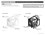
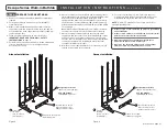
Alcove Installation
Corner Installation
STEP 3:
PREPARE THE POCKET AREA
1. Remove the existing tub and the wall and floor materials as
required.
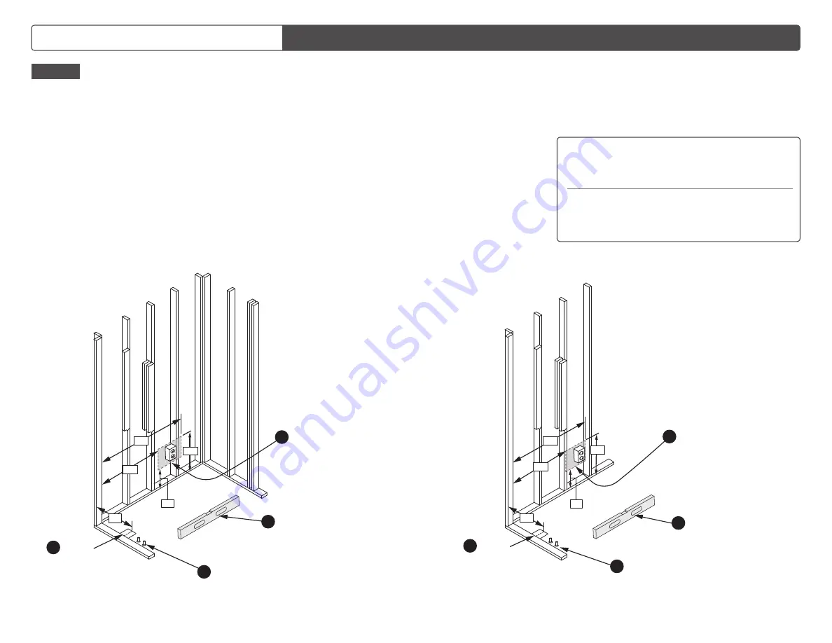
2. For rough pocket area dimensions, refer to installation
schematics below.
3. Make certain installation area has a flat surface that can
support the combined weight of the tub, the water and the
user; and that the wood support base will have full and level
contact with the floor.
4. Follow all safety requirements as referenced under
IMPORTANT: READ AND FOLLOW ALL SAFETY
INSTRUCTIONS
on page 2.
5. For built-in and custom units with water, air and microbubble
systems, install the unit so the electrical panel can be
accessed for servicing.
6. Have a licensed electrician install the power supply per these
instructions and per the requirements of the National Electrical
Code and the local authority having jurisdiction. Units
equipped with a water, air, or microbubble jet system, require
one dedicated circuit rated 20 amp/120 volt that is properly
grounded and protected by a suitable GFCI outlet and a 20A
circuit breaker.
Note:
If the O3 Ozone Sanitation System option is included,
the universal controller has a dedicated outlet for this plug.
7. Have a licensed plumber prepare the hot and cold water
supply lines and the connection to the drain plumbing so that
final connections can be made through an access opening
once the tub is in its final position. The hot and cold plumbing
connections and the drain, including the door drain outlet,
should be installed to local codes.
8. After the area is prepared and the floor is clean and level, the
tub can be moved into the pocket area.
9. For “reverse” plumbing (e.g., tub is placed in opposite
orientation to avoid tub door being blocked by toilet), the
drain plumbing may be run under the tub if necessary.
NOTE:
A "remote" P-trap may not meet state, provincial or
municipal plumbing code.
16"
36"
48"
10"
20"
Level the floor to ensure
all five leveling feet will
make good floor contact.
1
Prepare the hot and cold
water supply lines
3
Prepare
the drain
(min. 5" x 5" hole
for drain pipe)
2
Designated outlet area
(applies to jetted tubs only):
USA and Canada:
120V/20A GFCI outlet
4
Designated outlet area
(applies to jetted tubs only):
USA and Canada:
120V/20A GFCI outlet
4
16"
36"
48"
10"
20"
Level the floor to ensure
all five leveling feet will
make good floor contact
1
Prepare
the drain
(min. 5" x 5" hole
for drain pipe)
2
Prepare the hot and
cold water supply lines
3
(continued on page 6)
Figure 6
Figure 5
•
Connect only to a circuit protected by a Class A ground-fault
circuit-interrupter.
•
Connect only to a branch circuit protected by an overcurrent
protection device rated not more than 20 A.
•
Brancher seulement à une dérivation protégée par un
disjoncteur de fuite à la terre de Classe A.
•
Brancher à une dérivation protégée para un dispositif de
protection contre les surintensités d’au plus 20 A.


