Bespoke Infinity Скачать руководство пользователя страница 1

1

INSTALLATION 
MANUAL

Infinity Stairlift

Rail 
Carriage 
Seat

Huddersfield • England 

Содержание Infinity

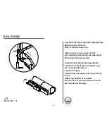
Страница 1: ...1 INSTALLATION MANUAL Infinity Stairlift Rail Carriage Seat Huddersfield England ...

Страница 2: ... commissioning lt is also assumed that the person using this manual will have the basic knowledge and skills required in both the mechanical and electrical aspects to apply consideration and awareness for the safety of themselves and others involving their work The contents of this manual are in the recommended order of placement which forms the full installation and commissioning of this standard...

Страница 3: ...eparation and Fixing 4 9 Carriage Preparation and Assembly 10 30 Calibrate and Program the Stairlift 31 35 Troubleshooting 36 39 Wiring Diagrams 40 Certificate of Conformity 41 Demonstration and Handover 42 Installation Tools 43 CONTENTS ...

Страница 4: ...ion Length Total Height 1 New 205 ABF 280 312 87 2 New 165 450 499 87 3 New 204 450 515 62 4 New 204 450 526 37 5 New 100 400 442 06 6 New 100 400 442 04 7 New 100 400 442 04 8 New 100 400 442 02 9 New 165 450 507 07 10 New 165 450 489 59 Installation Drawing RH EXT 180 Standard Start and Finish A3 SHEET 1 OF 3 DWG TITLE Revision DATE DO NOT SCALE DRAWING UNLESS OTHERWISE SPECIFIED DIMENSIONS ARE ...

Страница 5: ...5 Thread 2 core cable through lower tube of each section of rail working from top to bottom Ensure a minimum of 150mm of cable at each end RAIL PREPARATION ...

Страница 6: ...ld be flush with stair side of rail Fit and tighten joint clamps Using the installation drawing details Check top and bottom rail heights over the corresponding steps Check rail angles Check lower and upper rails are vertically in line Adjust leg heights as required Ensure rail to wall measurements match the Installation drawing RAIL FIXING ...

Страница 7: ...rews Figure 4 Tighten screw to leg Repeat for each leg The following fixings are recommended Timber Staircase 3 x 50mm screws Concrete Staircase 3 x 50mm screws 3 x rawlplugs Other Staircases Installation requirements must be assessed during Survey BE AWARE OF HIDDEN DANGERS SUCH AS WIRING PIPEWORK ETC RAIL FIXING ...

Страница 8: ...re all rail dimensions are in accordance with the rail installation drawing Carry out any final adjustment to the bases as required using the 3 x Grub Screws then tighten once the rail position is correct RAIL FIXING ...

Страница 9: ...ion near the power supply using the screws supplied Please ensure the charger is mounted level and secure Leave sufficient length on the power output to enable easy connection to the rail charge points Do not connect or switch on the power supply until the rail charge points have been connected See Page 31 Power Supply Charging Unit Power Output Cable ...

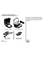
Страница 10: ...10 CARRIAGE PREPARATION ...

Страница 11: ...embled carriage and footrest seat arm assembly and EITHER a manual swivel or powered swivel boss assembly CARRIAGE PREPARATION CARRIAGE FOOTREST SEAT ARMREST ASSEMBLY MANUAL SWIVEL BOSS ASSEMBLY POWERED SWIVEL BOSS ASSEMBLY ...

Страница 12: ...riage is removed from the box insert the long loading bar into the top skate Fig 1 Insert the small cone into the bottom rail tube Loading bar cone are part of the separate installation kit Small cone Loading Bar Loading strap Fig 1 Fig 2 ...

Страница 13: ...13 CONTROL CABLE INSTALLATION LH Control LH Swivel RH Control RH Swivel LH Control RH Swivel RH Control LH Swivel RH LH RH LH RH LH RH LH ...

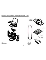
Страница 14: ...14 M8 x8 M5 x4 CABLE 1 Powered Swivel Unit Powered Swivel Board INSTALLATION OF THE POWERED SWIVEL UNIT ...

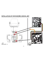
Страница 15: ...15 C OFF INSTALLATION OF THE POWERED SWIVEL UNIT Powered Swivel Board Powered Swivel Unit ...

Страница 16: ...16 INSTALLATION OF THE POWERED SWIVEL UNIT ...

Страница 17: ...17 INSTALLATION OF THE POWERED SWIVEL UNIT 2a 2b 3 1 1 2 4 3 RH 1 2 4 3 LH ON ...

Страница 18: ...18 INSTALLATION OF THE MANUAL SWIVEL LEVER In the Box ...

Страница 19: ...19 INSTALLATION OF THE MANUAL SWIVEL LEVER 1 2 ...

Страница 20: ...20 INSTALLATION OF THE MANUAL SWIVEL LEVER 3 ...

Страница 21: ...21 M8 x8 M5 x4 Manual Swivel Unit INSTALLATION OF THE MANUAL SWIVEL UNIT ...

Страница 22: ...22 C OFF INSTALLATION OF THE MANUAL SWIVEL UNIT ...

Страница 23: ...23 INSTALLATION OF THE MANUAL SWIVEL UNIT Connect the Swivel Micro switch as shown in the detail below ...

Страница 24: ...24 INSTALLATION OF THE MANUAL SWIVEL UNIT 2a 2b 3 1 1 2 4 3 1 2 4 3 RH LH ON ...

Страница 25: ...HE BATTERIES Remove the front panel by removing the 4 screws The battery housing is easily accessible behind the front panel Install the batteries as shown in Fig 1 Replace the front panel CARRIAGE ASSEMBLY FUSE Fig 1 ...

Страница 26: ...26 CARRIAGE ASSEMBLY RESET THE CHAIR On the main board hold down button 1 switch on the main switch Keep button 1 pressed down until an audible beep is heard BEEP ...

Страница 27: ... lift s main switch PRESS micro switch 3 ONCE 2 IMMEDIATELY Press and hold either directional button on the remote LED 3 will Illuminate continuously when programmed 3 Further remote controls will automatically be programmed as they are paired with each other PROGRAM THE REMOTE CONTROLS N O P ON PRESS ONCE LED 1 2 1 2 3 PRESS HOLD ...

Страница 28: ...e down the rail to a position that is accessible This will enable the seat and armrest component to be easily assembled Switch off the carriage by the main switch and disconnect the temporary remote The seat and armrest components are ready to be assembled CARRIAGE ASSEMBLY Fig 1 ...

Страница 29: ...entre of the boss carriage as illustrated in figure 1 and pass through to the front of the carriage Connect the joystick connector cable to the PCB cable as shown in figure 2 Be careful when connecting the two components that the cable is free to move as the seat swivels CARRIAGE ASSEMBLY Fig 1 Fig 2 ...

Страница 30: ...30 Mount the seat armrests assembly to the swivel boss using 4x M8x40 Cap head screws use Locktight threadlocker CARRIAGE ASSEMBLY ...

Страница 31: ...arger ATTENTION When placing the final end stops and charging points please ensure the following points 1 The lower skate of the carriage does not touch the floor before engaging with the final end stop This could result in damage to the skate mechanism 2 When the charging terminals are engaged make sure there is ONLY 5mm 10mm gap between the final end stop and the lower skate INSTALL RAIL CHARGE ...

Страница 32: ... check should be taken to ensure correct functionality Open the access panel located on the right side panel of the stairlift to view the main board Dip switch 2 should be in the OFF position for a left handed installation and in the ON for a right handed installation CALIBRATE THE STAIRLIFT ...

Страница 33: ...ift to its first terminal Downstairs Then stop the stairlift Fig 1 the stairlift will automatically stop on the charge terminal if the terminal is powered If an optional intermediate charge point is installed move the stairlift up to the charge point then stop Fig 2 PROGRAMMING THE STAIRLIFT STOP S T O P Fig 1 Fig 2 STO P stop STO P Optional ...

Страница 34: ...upstairs to final charging terminal Follow these steps when the stairlift is at its final charging terminal Switch off the stairlift Wait 10 seconds Switch the stairlift on Wait 5 seconds The stairlift is now ready to use PROGRAMMING THE STAIRLIFT STOP stop ...

Страница 35: ...st be programmed the following way Position the Stairlift where you would like to start the slowing function Push button 2 on the main PCB board until a beep is heard 2 Push 3 2 1 1 Stop 3 Move 5 Push 3 2 1 4 Stop Move the Infinity Stairlift Around the bend to the position where you would like the slowing function to stop then Push button 2 on the main PCB board until a beep is heard The unit will...

Страница 36: ...36 TROUBLESHOOTING ...

Страница 37: ...located on the left side of the carriage and locate the winding mechanism Engage the winding mechanism and manually turn the handle To release the over speed governor OSG wind the stairlift in the upwards direction to release the OSG arm MANUAL OVERRIDE ...

Страница 38: ...the lift upwards with the manual override the OSG should come loose from the tube then Make sure that the OSG is in neutral position again The unit does not need re programming RESET THE OSG DETAIL A SCALE 1 2 ...

Страница 39: ...irlift emits a selection of loud beeps to indicate what the problem is enabling the engineer to pinpoint the fault and resolve quickly without the need of elimination of other potential faults Fault Audible Beeps Safety Edges Left Right 1 Beep Chair Rotated 2 Beeps Not Charging 3 Beeps Invalid Move 4 Beeps Friction Wheel 5 Beeps Low Voltage 6 Beeps Over Current 7 Beeps OSG Continuous Beep All Erro...

Страница 40: ... nr 2 Black nr 3 Black nr 4 Black nr 1 Red Black Grey Grey Orange Orange Blue Blue Green Green Blue Blue Green Green Black nr 2 Black nr 4 Black nr 3 Black nr 1 Black Blue Brown 2 1 2 1 armrest sensor connect to armrest sensor B 1 2 3 4 5 6 6 3 2 5 4 1 6 3 2 5 4 1 6 3 2 5 4 1 7 8 9 10 1 2 3 4 3 1 4 2 1 2 2 1 2 1 2 1 1 2 4 3 Mainframe Brake Black Blue Green Red 4 2 1 3 connect Black Black White Red...

Страница 41: ...wing standards and specifications EN 81 40 2008 And the products to which this declaration relates are in conformity with the following EU directives Electro Magnetic Compatibility Directive 2004 108 EC Low Voltage Directive 2006 95 EC Machinery Directive 2006 42 EC Signed On Behalf of Bespoke Stairlifts Limited Date CERTIFICATE OF CONFORMITY Technical Documentation is available upon request from ...

Страница 42: ...r functions and when used should only swivel in the up direction as a safety measure On N0 occasion should the manual override function allow the user to swivel the chair in the down direction 8 Ask the user to sit comfortably on the seat and explain the use of the seatbelt the seatbelt should always by used Ensure the user does not extend their arm beyond the seat back 9 Ask the user to operate t...

Страница 43: ...heavy duty 15 External circlip pliers 16 Flat blade screwdrivers one set variable sizes 17 Hammer 20oz claw or ball pen 18 Long nose pliers 19 Magnetic angle finder 20 Digital Multi meter Clamp meter must be capable of measuring DC current at 30A for at least 5 seconds 21 Nut runners sizes 5mm 5 5mm 7mm 8mm 22 Stanley knife utility knife 23 Lube grease 24 Terminal screwdriver 25 Torque wrench driv...

Страница 44: ...44 Infinity Stairlift Rail Carriage Seat Huddersfield England ...

Отзывы: