background image

28

E N G L I S H

OPERATION

WARNING: To reduce the risk of injury, turn 
unit off and disconnect machine from power 
source 

before installing and removing acces-

sories, before adjusting or changing set-ups or 
when making repairs. Be sure the trigger switch 
is in the OFF position. An accidental start-up 
can cause injury.

Instructions for use

WARNING:

 Always observe the safety instruc-

tions and applicable regulations.

The attention of UK users is drawn to the “woodwork-
ing machines regulations 1974” and any subsequent 
amendments.

Prior to operation

WARNING:

• 

Install the appropriate saw blade. Do not 
use excessively worn blades. The maxi-
mum rotation speed of the tool must not 
exceed that of thesaw blade.

• 

Do not attempt to cut excessively small 
pieces.

• 

Allow the blade to cut freely. Do not 
force.

• 

Allow the motor to reach full speed before 
cutting.

• 

Make sure all locking knobs and clamp 
handles are tight.

• 

Secure the workpiece.

• 

Although this saw will cut wood and many 
nonferrous materials, these operating 
instructions refer to the cutting of wood 
only. The sameguide-lines apply to the 
other materials. Do not cut ferrous (iron 
and steel) materials or masonry with this 
saw! Do not use any abrasive discs!

• 

Make sure to use the kerf plate. Do not 
operate the machine if the kerf slot is wider 
than 10 mm.

• 

Placing the workpiece on a piece of wood 
will increase the capacities to 300 mm.

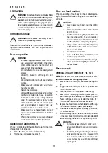
Switching on and off (fi g. 1)

A hole (cc) is provided in the on/off switch (a) for insertion 
of a padlock to lock the tool.
1.  To run the tool, press the on/off switch (a).
2.  To stop the tool, release the switch.

Body and hand position

Proper positioning of your body and hands when operat-
ing the mitre saw will make cutting easier, more accurate 
and safer.

WARNING:

• 

Never place your hands near the cutting 
area.

• 

Place your hands no closer than 150 mm 
from the blade.

• 

Hold the workpiece tightly to the table and 
the fence when cutting. Keep your hands in 
position until the switch has been released 
and the blade has completely stopped.

• 

Always make dry runs (without power) 
before fi nish cuts so that you can check 
the path of the blade.

• 

Do not cross your hands.

• 

Keep both feet firmly on the floor and 
maintain proper balance.

• 

As you move the saw arm left and right, 
follow it and stand slightly to the side of 
the saw blade.

Basic saw cuts

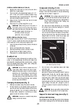
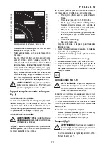
VERTICAL STRAIGHT CROSS CUT (FIG. 1, 20)

NOTE: Use 216 mm saw blades with 30 mm arbor holes 
to obtain the desired cutting capacities.

1.  Slacken the mitre latch (m) and subsequently lift it 

up.

2.  Engage the mitre latch (m) at the 0° position and 

fasten the mitre latch.

3.  Place the wood to be cut against the fence (p).
4.  Take hold of the carrying handle (c) and press the 

guard lock up release lever (b) to release the guard. 
Press the trigger switch (a) to start the motor. It is 
recommended to start the cut near the fence.

5.  Depress the head to allow the blade to cut through 

the timber and enter the plastic kerf plate (k).

6.  When the head is fully depressed, slowly pull it across 

to complete the cut.

7.  After completing the cut, release the switch and wait 

for the saw blade to come to a complete standstill 
before returning the head to its upper rest position.

WARNING:

• 

For some types of plastic profi les, it is 
advisable to follow the sequence in reverse 
order.

• 

The lower blade guard is designed to close 
quickly when the lever (b) is released. If it 
does not close within 1 second, have the 
saw serviced by an authorized Berner 
repair agent.

Содержание 61355

Страница 1: ...Instruction manual PANEELSAEGE BMS 777 Article Numbers 61355 88610 Languages en fr de it BERNER_Instruction_manual_PANEELSAEGE_BMS_ _777_66219 PDF _en pdf 2016 11 10 ...

Страница 2: ...tasítás Biztonsági előírások Приручник Сигурносна упутства Priručnik s uputama Sigurnosne upute Instrukciju rokasgrāmata drošības norādījumi Руководство по эксплуатации Правила техники безопасности Mašinos eksploatavimo vadovas Saugumo instrukcija Návod na obsluhu Bezpečnostné pokyny D KAPP UND GEHRUNGSSÄGE GB CROSS CUT MITRE SAW F SCIE TRONÇONNEUSE À ONGLET E SIERRA INGLETADORA DE CORTE TRANSVERS...

Страница 3: ... 32 Español 44 Portuguęs 56 Italiano 68 Nederlands 80 Dansk 92 Svenska 103 Norsk 114 Suomi 124 Eλληνικα 134 Türkçe 147 Polski 158 Česky 170 Magyar 181 Српски 192 Hrvatski 204 Lietošanas pamācība 215 Русский язык 226 Lietuvių kalba 240 Slovenčina 251 ...

Страница 4: ...3 aa v r y t w u v v z a b c d f e p o n l m j g k q q s cc i x cc h bb ee ee Figure 1 Figure 2 ...

Страница 5: ...4 Figure 7 Figure 3 Figure 4 Figure 8 Figure 5 Figure 6 Figure 9 Figure 10 gg hh ii kk ll ll mm ii mm oo qq pp q f e h ss aa bb z nn jj ff b g ...

Страница 6: ...5 Figure 11 Figure 12 Figure 13 Figure 14 Figure 15 Figure 16 n e m l n o ww vv uu tt i p t a3 xx h yy dd ...

Страница 7: ...6 Figure 17 Figure 18 Figure 19 Figure 20 xx h a4 u a1 a2 a2 zz dd a3 t ...

Страница 8: ...7 Figure 21 Figure 22 Figure 23 Figure 24 ...

Страница 9: ...mission wurde mittels eines standardisierten Prüfverfahrens gemäß EN 61029 gemessen und kann zum Vergleich verschiedener Werkzeuge verwendet werden SiekannfüreinevorläufigeExpositionsbewertung verwendet werden WARNUNG Der angegebene Schwingungs pegel steht für die Hauptverwendung des Werkzeugs Wird das Werkzeug für andere Anwendungen mit anderem Zubehör oder schlecht gewartet eingesetzt kann die Sc...

Страница 10: ...gen Sie für eine gute Beleuchtung des Arbeitsbereiches 250 300 Lux Benutzen Sie das Werkzeug nicht an Stellen an denen Brand oder Explosionsgefahr besteht z B in der Nähe von brennbaren Flüssigkeiten oder Gasen 3 Schutz vor Stromunfall Vermeiden Sie Kör perkontakt mit geerdeten Flächen z B Rohre Heizkörper Kochplatten und Kühlschränke Bei extremen Einsatzbedingungen z B bei hoher Luftfeuchtigkeit ...

Страница 11: ...ug nicht wenn Sie müde sind oder unter dem Einfluss von Medika menten oder Alkohol stehen 20 Kontrollieren Sie Ihr Werkzeug auf Beschädi gungen Überprüfen Sie vor Inbetriebnahme Gerät und Netzkabel sorgfältig um sicher zu sein dass es ordnungsgemäß funktionieren und die angestrebte Leistung erbringen wird Überprüfen Sie dieAusrich tung der beweglichen Teile deren Befestigung dass keine Teile Schutz...

Страница 12: ...sgewech selt und die Säge geprüft werden sollen ÜberprüfenSieregelmäßig dassdieLüftungsschlitze des Motors sauber und spanfrei sind Tauschen Sie die Tischeinlage aus wenn sie ver schlissen ist Trennen Sie die Maschine vor der Durchführung von Wartungsarbeiten und vor dem Sägeblattwechsel vom Netz Führen Sie niemals Reinigungs oder Wartungsarbei ten durch wenn das Gerät noch läuft und der Kopf nich...

Страница 13: ...gsarretierung n Drehteller Gehrungsarm o Gehrungswinkelskala p Beweglicher Werkstückanschlag q Spanabsaugmündung r Traversenarretierung s Hebel für die Kopfarretierung t Neigungsklemmengriff u Neigungsgradskala v Löcher für die Werkbankmontage w Arretierungsknopf x Traversen y Sägekopf z Inbusschlüssel aa Kabelklemme bb Kabel cc Bohrung für Vorhängeschloss dd Umgehungsknopf ee Tragegriff links und...

Страница 14: ...herstellen dass die Be festigungsschrauben nicht aus dem Plattenboden herausragen Die Sperrholzplatte muss auf der Auflageplatte der Werkbank bündig aufliegen Bei Befestigung der Säge auf Arbeitsflächen ist immer dafür zu sorgen dass sie nur an den Spannstellen wo sich die Be festigungslöcher befinden festgespannt wird Ein Festspannen der Säge an einer anderen Stelle stört den ordnungsgemäßen Betrieb ...

Страница 15: ...rührt Schalten Sie das Gerät nicht ein bevor Sie das nicht kontrolliert haben Einstellen des Anschlags Abb 13 Lösen Sie den Arretierknopf i durch Drehen entgegen dem Uhrzeigersinn Verschieben Sie den Werkstückan schlag p so dass das Sägeblatt ihn nicht berührt Drehen Sie dann den Anschlagarretierungsknopf entgegen dem Uhrzeigersinn fest Prüfen und Justieren des Sägeblatts mit dem Anschlag Abb 2 14...

Страница 16: ... die des Sägeblattes Versuchen Sie nicht extrem kleine Werk stücke zu sägen Üben Sie beim Schneiden keinen über mäßigen Druck auf das Sägeblatt aus Überlasten Sie die Säge nicht Lassen Sie den Motor vor Arbeitsbeginn stets auf volle Drehzahl beschleunigen Vergewissern Sie sich dass alle Fest spannknöpfe und hebel angezogen sind Sichern Sie das Werkstück Obwohl diese Säge Holz und viele andere NE W...

Страница 17: ...t wenn der Hebel b losgelassen wird Schließt sie sich nicht innerhalb von 1 Sekunde lassen Sie die Säge durch einen autorisierten Berner Kundendienst mitarbeiter warten VERTIKALER GEHRUNGSSCHNITT ABB 21 1 Drücken Sie die Gehrungsarretierung m Bewegen Sie den Arm nach links oder nach rechts zum benö tigten Winkel 2 Die Gehrungsverriegelung rastet automatisch sowohl links als auch rechts bei 0 15 22...

Страница 18: ...en Sie dann einer geraden Linie um den richtigen Gehrungswinkel zu finden 0 5 10 15 20 25 30 35 40 45 0 5 10 15 20 25 30 35 40 45 5 10 15 20 25 30 35 40 45 5 10 15 20 25 30 35 40 5 10 15 20 25 30 35 40 4 5 5 0 5 5 6 0 6 5 70 75 80 85 5 10 15 20 25 30 35 40 4 5 5 0 5 5 6 0 6 5 70 75 80 85 5 10 15 20 25 30 35 40 4 5 5 0 5 5 6 0 6 5 70 75 80 85 ACHTSEITIGER KASTEN SECHSSEITIGER KASTEN WINKEL DER KASTE...

Страница 19: ...gsstellemitangeschlos senem aber nicht laufenden Gerät zu messen Optional ist ein separates Staubsystem erhältlich 1 Passen Sie die Staubabsaugrohre pp den Mün dungen q an Der längere Schlauch an die obere Mündung 2 Schließen Sie die Schläuche an den Dreiwegean schluss qq an Transport Abb 1 WARNUNG Für den Transport der Geh rungssäge sind im Fuß zwei Griffmulden ee vorgesehen 1 Für den Transport s...

Страница 20: ...ienen des Tisches an der Seite an der Sie den Tisch verwenden Beachten Sie alle mit dem Rollentisch mitgelieferten Anweisungen BEREICHE LIEFERBARER SÄGEBLÄTTER EMPFOHLENE SÄGEBLÄTTER Sägeblattabmes sungen Verwendung Durchmesser x Bohrung x Anzahl Zähne 216x30x24 Allgemeine Zwecke Ablängen und gerades Schneiden von Holz und Kunststoffen 216x30x80 TCG für Aluminiumbearbeitung 216x30x48 ATB für Feins...

Страница 21: ...al Kaufbeleg nach gewiesen werden muß In dieser Zeit garantieren wir Kostenlose Beseitigung eventueller Störungen Kostenlosen Ersatz aller schadhaften Teile Kostenlosen und fachmännischen Reparaturser vice Voraussetzung ist dass es sich um Material und oder Herstellungsfehler handelt und dass keine unsachge mäße Behandlung vorliegt Weiterhin dürfen nur Ori ginal Zubehörteile verwendet werden die a...

Страница 22: ... may be used to compare one tool with another It may be used for a preliminary assessment of exposure WARNING The declared vibration emission level represents the main applications of the tool However if the tool is used for different ap plications with different accessories or poorly maintained the vibration emission may differ This may significantly increase the exposure level over the total work...

Страница 23: ...n not involved in the work touch the tool or the extension cord and keep them away from the work area 5 Store idle tools When not in use tools must be stored in a dry place and locked up securely out of reach of children 6 Do not force the tool It will do the job better and safer at the rate to which it was intended 7 Use the right tool Do not force small tools to do the job of a heavy duty tool D...

Страница 24: ...vel well maintained and free of loose materials e g chips and cut offs Use correctly sharpened saw blades Observe the maximum speed mark on the saw blade Make sure all locking knobs and clamp handles are tight before starting any operation Never place either hand in the blade area when the saw is connected to the electrical power source Never attempt to stop a machine in motion rapidly by jamming ...

Страница 25: ...ech and MDF Package contents The package contains 1 Partly assembled machine 2 Allen key 4 6mm 1 216mm TCT saw blade 2 Dust extraction nozzles 1 Dust bag 1 Instruction manual 1 Exploded drawing Check for damage to the tool parts or accessories which may have occurred during transport Take the time to thoroughly read and understand this manual prior to operation Description fig 1 2 9 WARNING Never m...

Страница 26: ...s of most good quality plugs Attach the wires to their respective points in the plug see below Brown is for Live L 2 and Blue is for Neutral N 4 Before replacing the top cover of the mains plug ensure that the cable restraint 3 is holding the outer sheath of the cable firmly and that the two leads are correctly fixed at the terminal screws WARNING NEVER use a light socket NEVER connect the live L or...

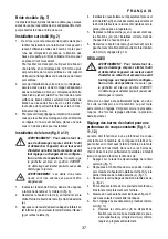
Страница 27: ...ly on the clamping bosses where the mounting screw holes are located Clamping at any other point will interfere with the proper operation of the saw 3 To prevent binding and inaccuracy be sure the mounting surface is not warped or otherwise uneven If the saw rocks on the surface place a thin piece of material under one saw foot until the saw is firm on the mounting surface Mounting the saw blade fig...

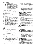
Страница 28: ...ng table mitre arm n 3 Swing the mitre arm until the latch locates it at the 0 mitre position 4 Pull down the head and lock it in this position using the lock down button w 5 Check that the two 0 markings ww on the mitre scale o are just visible 6 Place a square xx against the left side of the fence p and blade h WARNING Do not touch the tips of the blade teeth with the square 7 If adjustment is r...

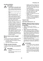
Страница 29: ...r positioning of your body and hands when operat ing the mitre saw will make cutting easier more accurate and safer WARNING Never place your hands near the cutting area Place your hands no closer than 150mm from the blade Hold the workpiece tightly to the table and the fence when cutting Keep your hands in position until the switch has been released and the blade has completely stopped Always make...

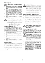
Страница 30: ...possible You can clamp to either side of the saw blade remember to position your clamp against a solid flat surface of fence WARNING Always use a material clamp when cutting non ferrous metals Compound mitre fig 23 24 This cut is a combination of a mitre and a bevel cut This is the type of cut used to make frames or boxes with slanting sides like the one shown in figure 23 WARNING If the cutting angl...

Страница 31: ...tion tube at the point of con nection with the tool connected but not running A separate dust kit is available as an option 1 Fit the dust extraction tubes pp to the nozzles q the longer hose to upper nozzle 2 Connect the hoses to the three way connector qq Transporting fig 1 WARNING In order to conveniently carry the mitre saw the base is provided with two hand indentations ee 1 To transport the s...

Страница 32: ...f no further use to you do not dispose of it with household waste Make this product available for separate collection Separate collection of used products and packaging allows materials to be recycled and used again Re use of recycled materials helps prevent environmental pollution and reduces the demand for raw materials Local regulations may provide for separate collection of electrical products...

Страница 33: ... fiche technique a été mesuré conformément au test standardisé proposé par EN 61029 et peut être utilisé pour comparer les outils entre eux Il peut être utilisé pour effectuer une étude d impact du degré d exposition AVERTISSEMENT Le taux d émission de vibrations indiqué s applique aux principales utilisations de l outil Cependant si l outil est utilisé pour d autres applications avec différents ac...

Страница 34: ...s ou de gaz inflammables 3 Attention aux décharges électriques Éviter tout contact corporel avec des éléments mis à la terre comme tuyaux radiateurs cuisinières électriques ou réfrigérateurs Dans des conditions de travail extrêmes ex humidité élevée production de limaille etc la sécurité électrique peut être améliorée par l utilisation d un transformateur d isolement ou d un disjoncteur différentie...

Страница 35: ...ceptible de nuire au bon fonctionnement de l outil Tout dispositif de protection ou autre pièce endommagé doit être réparé correctement ou remplacé par un centre de réparation agréé sauf indication contraire incluse dans ce manuel Faire remplacer tout interrupteur défectueux par un centre de réparation agréé Ne pas utiliser un outil dont l interrupteur est défectueux Ne jamais essayer de le répare...

Страница 36: ...exposition au bruit ex utilisation de lame spécialement conçue pour réduire le bruit maintenance de la lame et de l appareil Signaler immédiatement tout problème avec l appareil y compris dispositifs de protection ou lame de scie Offrir un éclairage général ou localisé adé quat S assurer que l opérateur est proprement formé pour l utilisation le réglage et l opération de l appareil Lorsque l appar...

Страница 37: ...pond bien à la tension indiquée sur la plaque signalétique Cet outil à double isolation est conforme à la norme EN 61029 un branchement à la terre n est donc pas nécessaire Si le câble doit être remplacé le faire changer par un réparateur agréé ou un électricien qualifié L utilisation des câbles suivants est obligatoire BMS 777 H07RN F 2x1 mm CH Toujours utiliser la fiche prescrite lors du rem place...

Страница 38: ...la tête car ter inférieur b pour relever le carter de lame inférieur g et retirez la lame h 4 Installez la nouvelle lame sur l épaulement prévu sur la bride Interne ff en vous assurant que les dents sur les bords inférieurs de la lame sont orientées vers le guide côté opposé à l opérateur 5 Replacez la bride externe e en vous assurant que les fixations ss sont installées correctement de chaque côté...

Страница 39: ...iquez une équerre xx contre le plateau et une autre contre la lame h fig 17 AVERTISSEMENT Ne pas mettre les pointes des dents en contact avec l équerre 4 Si un réglage s impose procédez comme suit a Desserrez la manette de serrage de chanfrein t puis tournez la vis de butée de réglage vertical zz vers la droite ou la gauche jusqu à ce que la lame soit à 90 du plateau comme déterminé par l équerre b...

Страница 40: ...upes Ne pas approcher les mains à moins de 150mm de la lame Maintenir la pièce près du plateau et du guide pendant la coupe Conserver les mains dans la même position jusqu à ce que l interrupteur soit relâché et la lame complètement arrêtée Faire systématiquement un essai hors secteur avant d effectuer la coupe finale pour vérifier la trajectoire de la lame Ne pas entrecroiser les mains Maintenir so...

Страница 41: ... lente et régulière produiront les résultats escomptés AVERTISSEMENT S assurer que le matériau ne glisse pas pendant la coupe l arrimer soli dement en place Attendre systématiquement que la lame s arrête complètement avant de lever le bras de scie Si de petites fibres de bois sont visibles à l arrière de la pièce à travailler appliquer un morceau de ruban adhésif là où la coupe sera effectuée Scier...

Страница 42: ...r des pièces longues lorsque la scie est utilisée par elle même les divers éléments sont en option Ces éléments sauf les pieds et la fixation de matériau sont requis à la fois du côté entrée et du côté sortie Pieds mm fourni avec un guide d assem blage Rails de guidage 500 ou 1 000mm hh Socles ll pour supporter les rails de guidage Ne pas utiliser les socles pour supporter la machine La hauteur des...

Страница 43: ...ne partie de l outil dans un liquide AVERTISSEMENT Pour réduire tout risque de dommage corporel nettoyer régulièrement votre établi AVERTISSEMENT Pour réduire tout risque de dommage corporel nettoyer régulièrement le système de dépoussiérage Accessoires en option AVERTISSEMENT Comme les accessoires autres que ceux proposés par Berner n ont pas été testés avec ce produit leur utilisation avec cet a...

Страница 44: ...illage piece de recharge ou accessoires sont contrôlés a fonds avant l expédition de l usine Si malgré cela vous trouviez des défauts envoyez la piece défectueuse a notre centrale pour clients ou dans l atelier de réparation contractuel de la société Berner le plus proche Le délai de garantie de 36 mois commence par le jour d achat ce que doit etre prouvé par l original du document d achat Pendant...

Страница 45: ...o in questa scheda è sta to misurato secondo lo standard definito nella EN 61029 e va utilizzato per confrontare un utensile con un altro Va utilizzato per una stima preliminare dell esposizione AVVERTENZA il livello di vibrazione emessa dichiarato vale per le attività principali dell uten sile Quando l utensile viene utilizzato per dif ferenti attività con accessori diversi o ha avuto scarsa manut...

Страница 46: ...gersi da scosse elettriche Evitare il contatto con superfici collegate con la terra per esempio tubature termosifoni fornelli e frigoriferi Durante l impiego in condizioni estreme per esempio ele vata umidità produzione di sfridi metallici ecc la sicurezza elettrica viene aumentata inserendo un trasformatore di isolamento o un interruttore salvavita FI 4 Tenere a distanza altre persone Non far tocc...

Страница 47: ...n cercare mai di far riparazioni da sé AVVERTENZA L utilizzo di qualsiasi accessorio o di aggiunta o l esecuzione di qualsiasi operazione con questo utensile in modo diverso da quanto raccomandato nelle istruzioni comporta rischio di lesioni personali 21 Far riparare l utensile da personale qualificato Questo apparato elettrico è conforme alle relative norme di sicurezza Le riparazioni dovrebbero e...

Страница 48: ...ll uso alla regolazione ed al funzionamento della macchina In caso di laser interno non sono consentite sostituzioni con laser di tipo differente Le riparazioni devono essere eseguite esclusiva mente presso il produttore del laser o un centro autorizzato Rischi residui I seguenti rischi sono inerenti all utilizzo di seghe lesioni causate dal toccare le parti in movimento Nonostante l applicazione ...

Страница 49: ...ori BMS 777 H07RN F 2 x 1 0 mm CH Per la sostituzione del cavo di alimentazione utilizzare sempre la spina di tipo prescritto Tipo 11 per la classe II doppio isolamento utensili elettrici Tipo 12 per la classe I messa a terra utensili elettrici CH Gli apparecchi portatili utilizzati in ambiente esterno devono essere collegati ad un inter ruttore differenziale Utilizzo di un cavo di prolunga Se è n...

Страница 50: ...siano inserite corret tamente una per ciascun lato dell albero motore 6 Stringere il bullone della lama f girando in senso antiorario mentre si tiene inserita la chiave a brugola da 6 mm z con l altra mano fig 10 REGOLAZIONI AVVERTENZA per ridurre il rischio di in fortuni spegnere l unità e disconnettere la macchina dall alimentazione prima di installa re e rimuovere accessori prima di regolazioni ...

Страница 51: ...e t e girare la vite di fermo di regolazione della posizione ver ticale zz in dentro o in fuori fin quando la lama è a 90 come misurato con la squadretta b Se l indice di inclinazione a1 non punta sullo zero della scala di inclinazione u allentare le viti a2 che assicurano la scala e muovere la scala e riallinearla Verifica e regolazione dell angolo di inclinazione fig 1 2 18 19 L esclusione dell inc...

Страница 52: ...ama Tagli di base della troncatrice TAGLIO A TRONCARE VERTICALE DRITTO FIG 1 20 NOTA utilizzare lame da 216 mm con foro per albero da 30 mm per ottenere le capacità di taglio desiderate 1 Allentare il blocco dell angolazione m e successi vamente sollevarlo 2 Inserire il blocco dell angolazione m nella posizione 0 e stringere il blocco 3 Posizionare il legno da tagliare contro la battuta p 4 Impugn...

Страница 53: ...lama ricordare di posizionare il morsetto contro una superficie di battuta piatta e solida AVVERTENZA utilizzare sempre un morsetto per materiali quando si tagliano metalli non ferrosi Taglio in diagonale composto fig 23 24 Questo taglio è una combinazione di un taglio in diagonale e uno inclinato E il tipo di taglio utilizzato per costruire cornici o scatole con lati obliqui come quella mostrata in...

Страница 54: ...e la lunghezza dei pezzi da lavorare medi e lunghi Può essere posto di fianco o ribaltato sotto al piano quando non si usa Aspirazione delle polveri fig 1 6 AVVERTENZA laddove possibile collegare un dispositivo di aspirazione delle polveri pro gettato secondo le norme relative all emissione di polveri Collegare un dispositivo di raccolta delle polveri progettato secondo le norme relative La velocità...

Страница 55: ...olo a rulli richiede l uso del piedistallo opzionale fig 3 AVVERTENZA montare il tavolo a rulli seguen do le istruzioni fornite con il piedistallo Sostituire le barre di supporto corte fornite con il piedistallo con i binari asimmetrici provenienti dal lato del tavolo che va utilizzato Seguire tutte le istruzioni fornite con il tavolo a rulli LAME DISPONIBILI RACCOMANDATE Dimensioni lama Utilizzo d...

Страница 56: ...nizia al giorno di compra il che deve essere provato con l originale del documento d acquisto Il produttore risponde durante il periodo di garanzia di eliminazione gratuita di eventuali avarie sostituzione gratuita di tutti i pezzi danneggiati assistenza gratuita e professionale Il requisito è che questi siano materiali e o difetti di pro duzione e che non vi sia stato alcun uso inappropriato dell...

Страница 57: ...in Berner Montaje y Fijación S L Poligono Industrial La Rosa VI C Albert Berner núm 2 E 18330 Chauchina Granada Tel 34 958 060 200 Fax 34 902 11 31 92 email bernerspain berner es www berner es F France Berner S à r l ZI Les Manteaux F 89331 Saint Julien du Sault Cedex Tel 33 38 69 94 400 Fax 33 38 69 94 444 email contact berner fr www berner fr FIN Finland Berner PULTTI OY Volttikatu 6 70700 Kuopi...

Страница 58: ...o berner pl www berner pl S Sweden Albert Berner Montageteknik AB Kumla Gärdsväg 18 S 14563 Norsborg Tel 46 85 78 77 800 Fax 46 85 78 77 805 email info berner se www berner se SK Slovakia Berner s r o Jesenského 1 SK 962 12 Detva Tel 421 45 54 10 245 Fax 421 45 54 10 255 Email berner berner sk www berner sk TR Turkey Berner Endüstriyel Ürünler Sanayi ve Ticaret A Ş Ferhatpaşa Mah G7 Sok 31 2 TR 34...

Отзывы: